DECAN_S1_Administrator′s_Guide(Eng_Ver1.5)_Print.pdf - 第440页
14-58 Next Generation, Multi-Functional Plac er DECAN S1 Administrator’s Guide Memo The reference values fo r the calibration of the Camera Of fset is as follows. Gantry 1 Offset X: -189.5 ~ -187.5 (mm) Offset Y : -1.0…
14-57
Machine Calibration
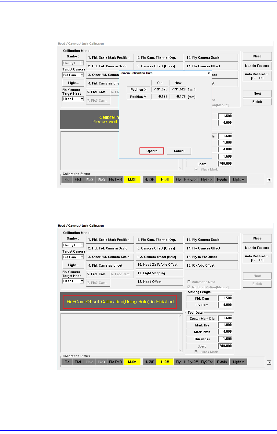
5. The calibration is performed automatically. If it is completed, the calibration result
is displayed as shown in the following figure. Click the <Update> button to apply
the new calibration value.
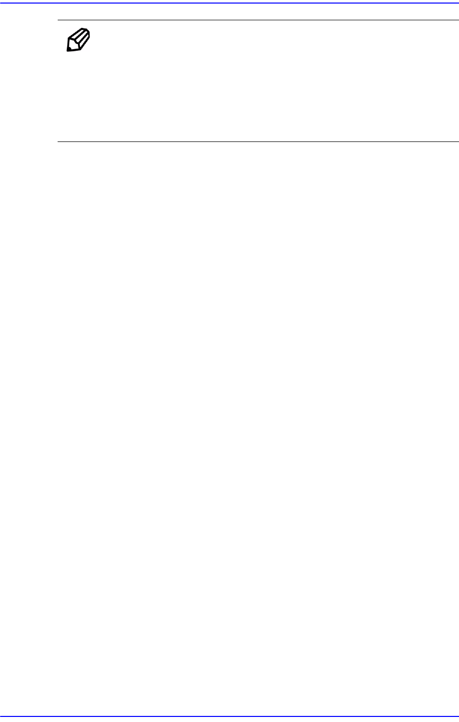
6. If the calibration procedure is completed properly, the result as shown in the
following figure is displayed and then the message, “Fid-Cam Offset
Calibration(Using Hole) is Finished.”.
14-58
Next Generation, Multi-Functional Placer DECAN S1 Administrator’s Guide
Memo The reference values for the calibration of the Camera Offset is as
follows.
Gantry 1
Offset X: -189.5 ~ -187.5 (mm)
Offset Y: -1.0 ~ 1.0 (mm)
14-59
Machine Calibration
14.3.8.4. Head Z / R Offset Calibration
The distance from the upper surface of the PCB to the Z axis home is set mechanically. For
the Z offset calibration, measure the offset for this distance based on the upper surface of
the PCB by using pneumatic pressure.
For the R offset calibration, measure the offset of the angle to align the nozzle holder
based on zero (0) degrees.
The following is the process that the Z offset calibration is performed. The nozzle used for
calibration is the CN040 nozzle.
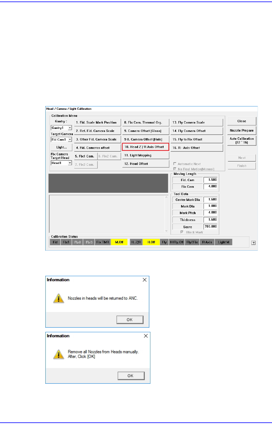
1. Click the <10. Head Z / R Axis Offset> button.
2. Click the <Nozzle Prepare> button and remove all nozzles inserted in the nozzle
holders of all heads. Insert the CN040 nozzle into the No. 16 hole of the ANC.