DECAN_S1_Administrator′s_Guide(Eng_Ver1.5)_Print.pdf - 第444页
14-62 Next Generation, Multi-Functional Plac er DECAN S1 Administrator’s Guide The following is the procedure to perform the ‘R-Of fset Calibration’. 1. Assign nozzle CNT0 to ANC Hole No.1. 2. In the <Grid> group, …
14-61
Machine Calibration
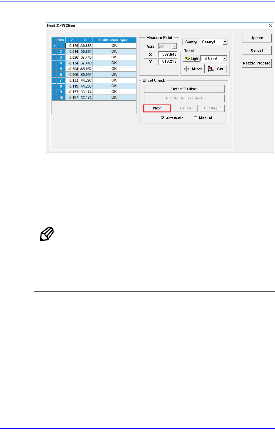
4. Click the <Next> button.
5. The head moves to the designated position on the ANC automatically. Then the
machine creates pneumatic pressure and performs calibration while moving the
spindle down from Head 1 to Head 10 in order.
6. If the calibration is completed, the calibration result is reflected on the Z column of the
<Grid> group automatically.
Click the <Update> button to apply the calibration result to the machine.
Memo The reference values for the Z-offset are as follows.
Head 1~ Head 10: -1.5 ~ 1.5 mm
If the Z offset value exceeds this range, it means that the head has a
serious problem. Therefore, check for the home location, spindle,
LM, and verify if the motor operates normally.
14-62
Next Generation, Multi-Functional Placer DECAN S1 Administrator’s Guide
The following is the procedure to perform the ‘R-Offset Calibration’.
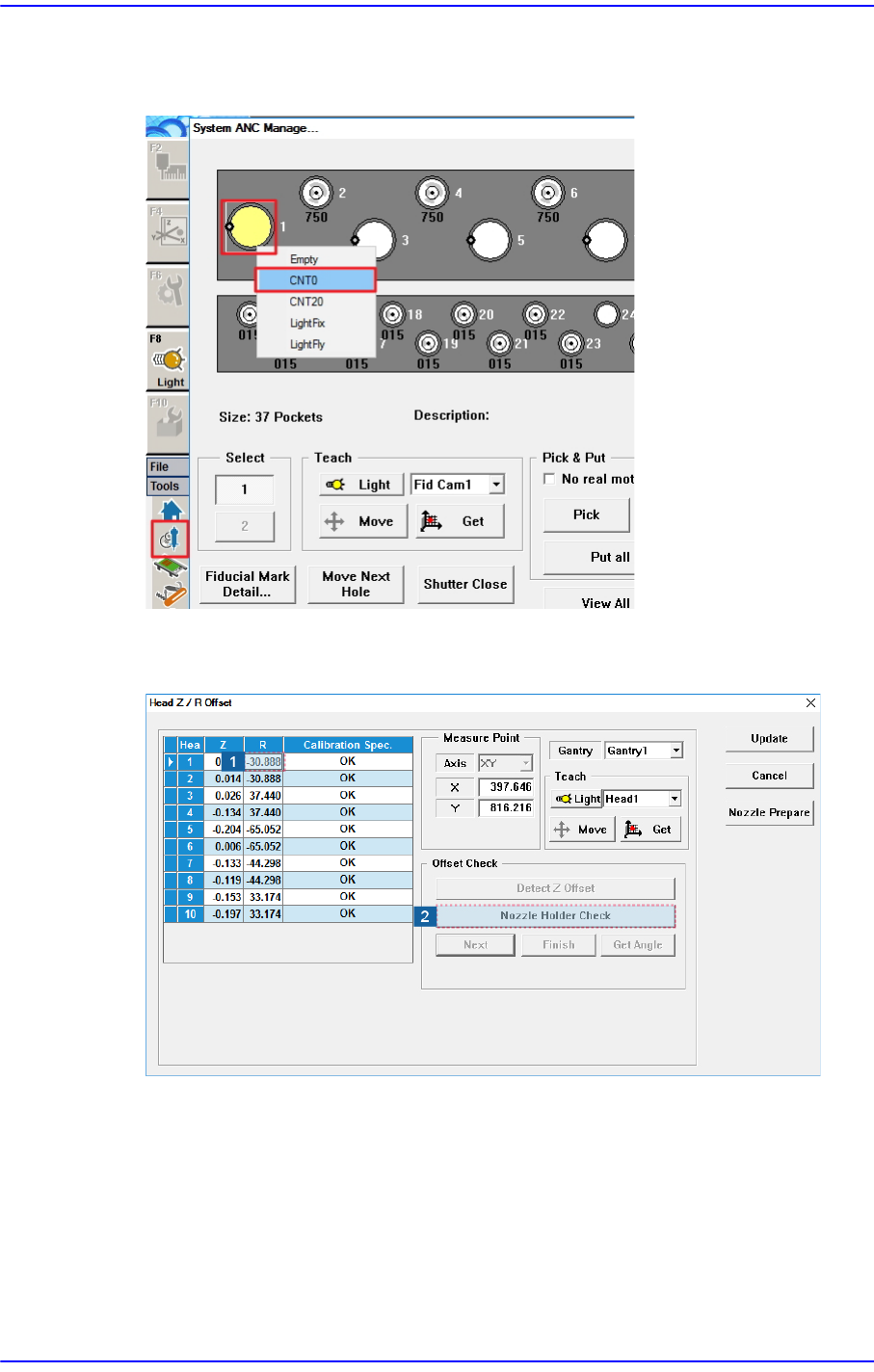
1. Assign nozzle CNT0 to ANC Hole No.1.
2. In the <Grid> group, select the R-axis for which the calibration is to be performed and
click the <Nozzle Holder Check> button.
3. Then the message “First, We must Put all Nozzles from Heads manually. To Moving
Down Z Axis, Click [Next].” appears in the message window. Remove all nozzles
inserted in the nozzle-holder manually by clicking the <Next> button.
At this time, for the ANC, the virtual nozzle CNT0 is set for the No. 1 hole of the ANC
and it is regarded that the corresponding head picked the CNT0 nozzle.
14-63
Machine Calibration
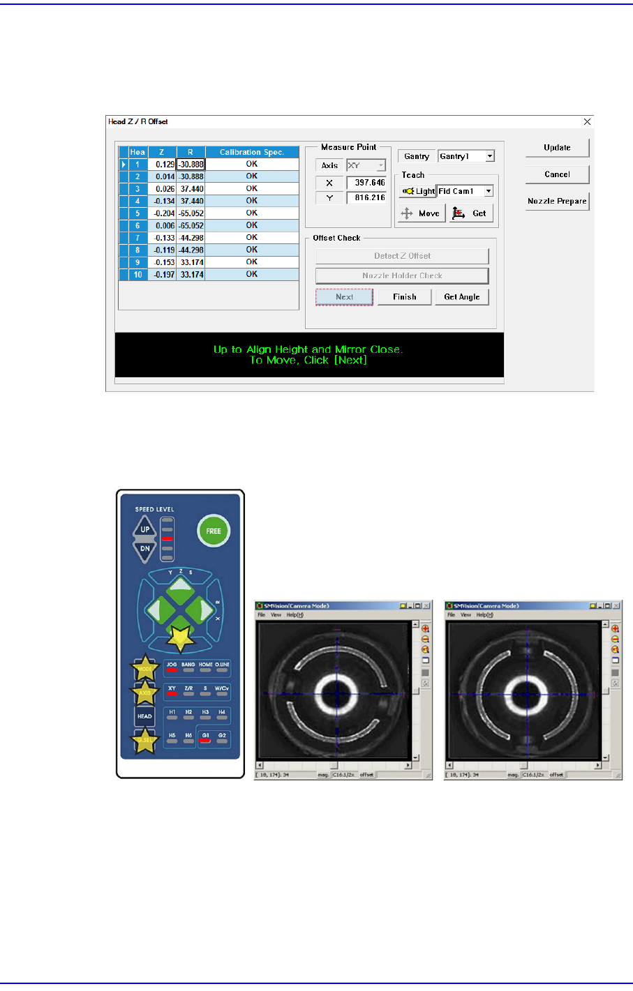
4. Then the message “Up to Align Height and Mirror Close. To Move, Click [Next].”
appears. Then move the spindle to the part recognition height so that the nozzle holder
of the head can be seen from the fly camera and click the <Next> button to close the
mirror.
5. Rotate the spindle in the R-direction by using the teaching box so that the shape of the
nozzle holder becomes ‘( )’. At this time, the nozzle holders of the heads with
interlocked mechanism must be assembled in the same direction.
That is, the mechanisms of the #1~#2 heads and #3~#4 heads, #5~#6 heads, #7~#8
heads, #9~#10 heads must be assembled first in the same direction by using the jig for
a nozzle holder.