DECAN_S1_Administrator′s_Guide(Eng_Ver1.5)_Print.pdf - 第447页
14-65 Machine Calibration 14.3.8.6. Head Offset Calibration Measure the distance (XY Of fset) betwe en the center of the gantry fi ducial camera and the center of each head. T o perform XY Offset Calibration of each head…
14-64
Next Generation, Multi-Functional Placer DECAN S1 Administrator’s Guide
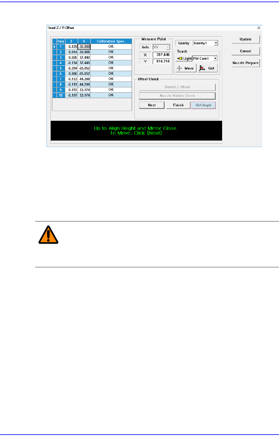
6. Click the <Get Angle> button in the <Offset Check> group to input the R offset.
7. Perform the calibration form Head 2 to Head 10 in the same manner.
8. Click the <Update> button to apply the calibration result to the machine.
14.3.8.5. Light [F8]
Calibrate the brightness of the illumination for the fly camera and fix camera. For more
information please refer to “15.4. Light [F8]”.
Caution Since the nozzle for the SM32x model is not compatible to
the one for the light mapping used for the SM32x model, do
not use it for this machine.
14-65
Machine Calibration
14.3.8.6. Head Offset Calibration
Measure the distance (XY Offset) between the center of the gantry fiducial camera and the
center of each head.
To perform XY Offset Calibration of each head, first confirm that the CNT20 nozzle is
installed in ANC Hole No.1 before operation.
The following is the procedure to calibrate the XY offset of the head;
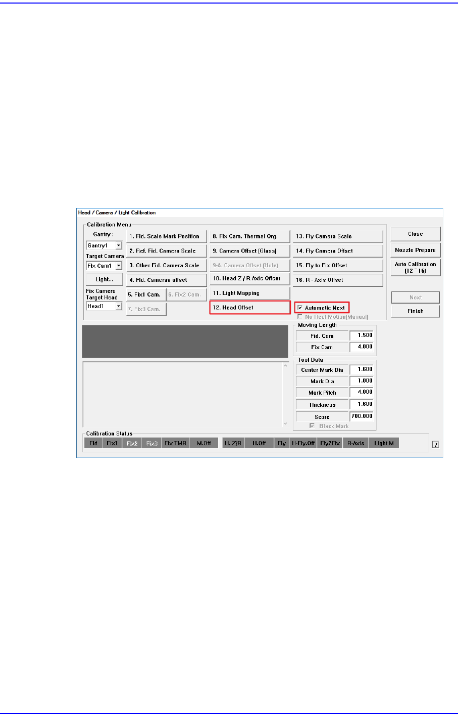
1. If the CNT20 nozzle is not installed, click the <Nozzle Prepare> button to manually
insert the CNT20 nozzle into ANC Hole No.1.
2. If the <12. Head Offset> is clicked after selecting the <Automatic Next> check box,
calibration is performed for the selected gantry automatically.
14-66
Next Generation, Multi-Functional Placer DECAN S1 Administrator’s Guide
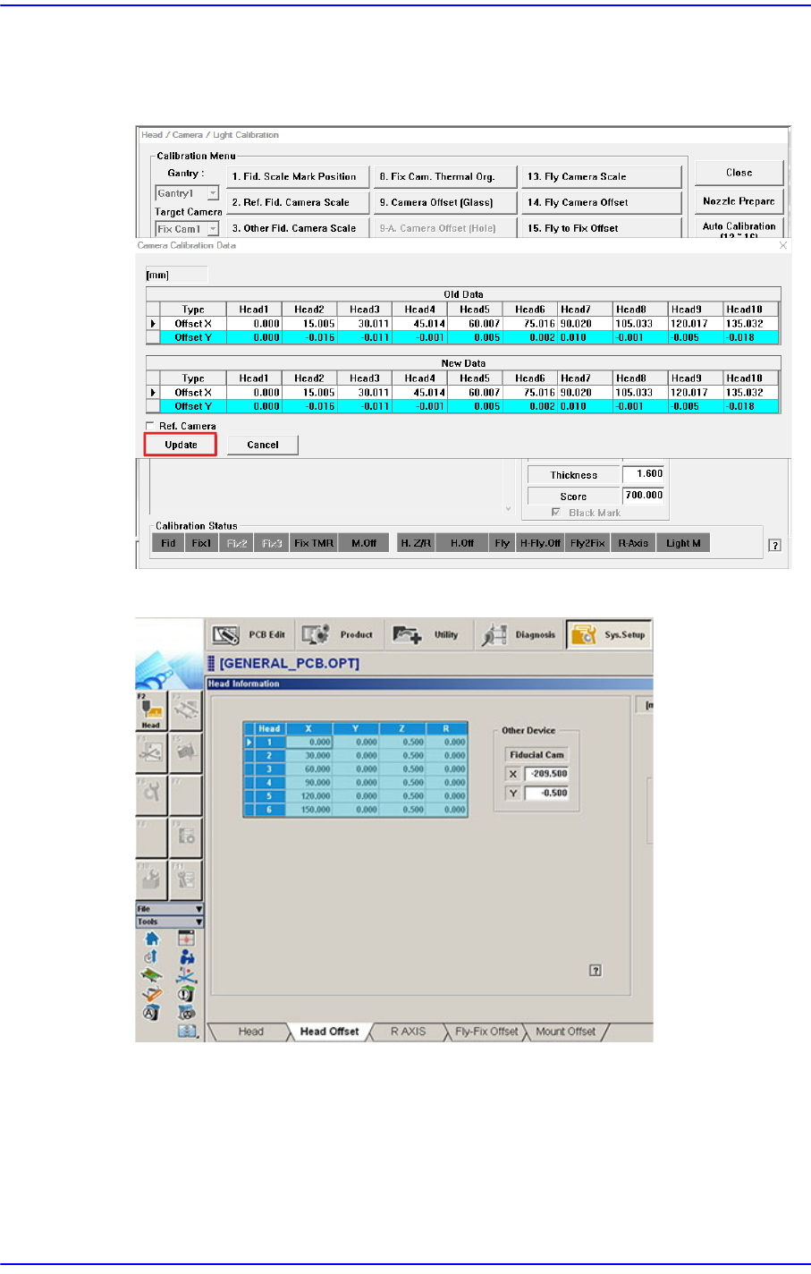
3. If the calibration procedure is completed for all heads normally, the result is displayed
as shown in the following figure. Click the <Update> button to apply the calibration
value.
The measurement result can be confirmed in the Head Offset dialog box.