DECAN_S1_Administrator′s_Guide(Eng_Ver1.5)_Print.pdf - 第450页
14-68 Next Generation, Multi-Functional Plac er DECAN S1 Administrator’s Guide 14.3.8.7. Fly Camera Scale Calibration This calibration is performed to find the scale and rotation offset of the fly-camera. T o perform Fly…
14-67
Machine Calibration
Memo The range of the reference value for the ‘Head XY Offset
Calibration’ are as follows:
Offset X (mm)
Head 1: -0.06 ~ 0.06
Head 2: 14.94 ~ 15.06
Head 3: 29.04 ~ 30.06
Head 4: 44.94 ~ 45.06
Head 5: 59.94 ~ 60.06
Head 6: 74.94 ~ 75.06
Head 7: 89.94 ~ 90.06
Head 8: 104.94 ~ 150.06
Head 9: 119.94 ~ 120.06
Head 10: 134.94 ~ 135.06
Offset Y (mm)
Head1 ~ 10: -0.05 ~ 0.05
14-68
Next Generation, Multi-Functional Placer DECAN S1 Administrator’s Guide
14.3.8.7. Fly Camera Scale Calibration
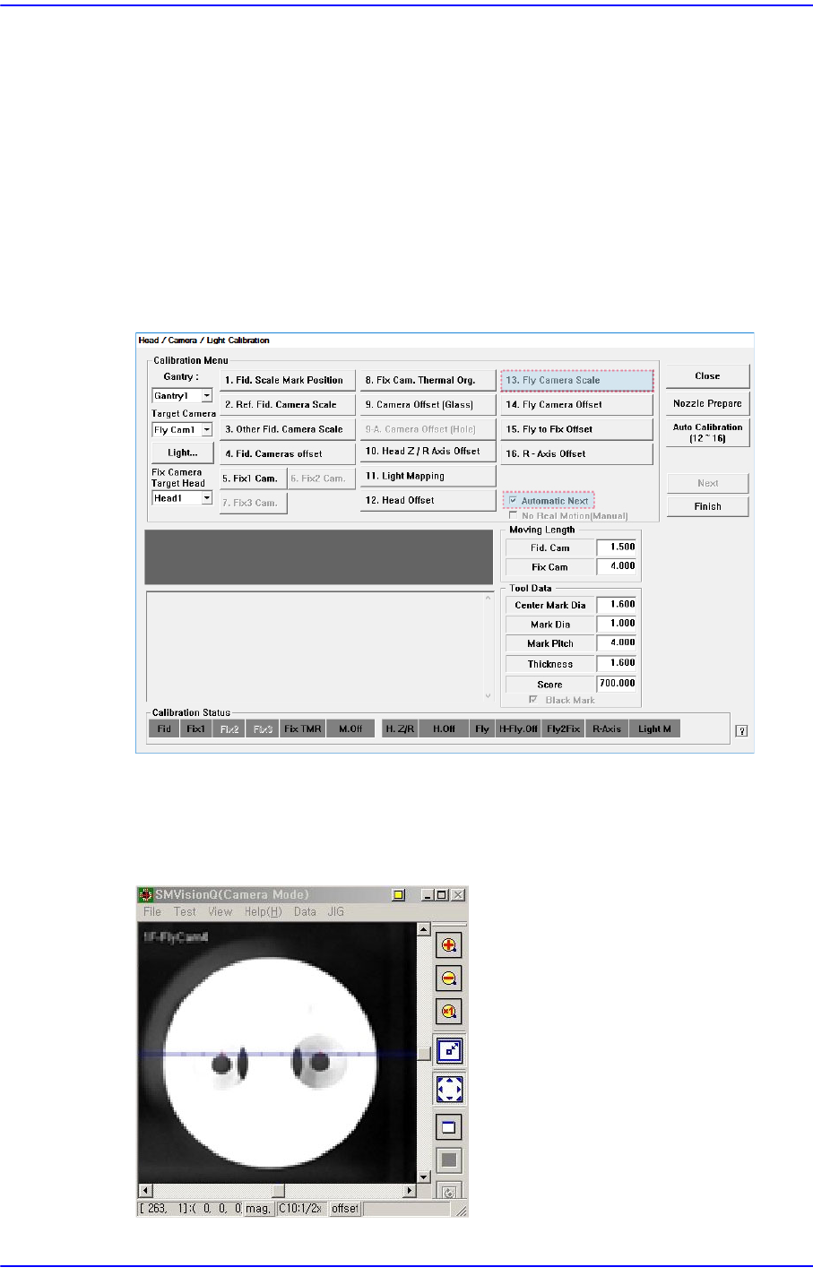
This calibration is performed to find the scale and rotation offset of the fly-camera. To
perform Fly-Camera Scale Calibration, first confirm that the CNT20 nozzle is installed in
ANC Hole No.1 before operation.
The following is the procedure to calibrate the ‘Fly-Camera Scale Calibration’
1. If the CNT20 nozzle is not installed, click the <Nozzle Prepare> button to manually
insert the CNT20 nozzle into ANC Hole No.1.
2. If the <13 Fly Camera Scale> is clicked after selecting the <Automatic Next> check
box, calibration is performed for the selected gantry automatically.
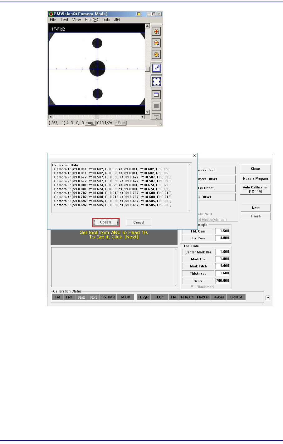
3. In order to perform calibration, recognize the 2 fiducial marks on the bottom surface
of the calibration tool using the fly camera and put the calibration tool on the calibra-
tion tool position on the ANC. Next, recognize the 2 fiducial marks at the edge of the
top surface of the calibration tool.
14-69
Machine Calibration
4. If the calibration procedure is completed for all fly-cameras normally, the result is
displayed as shown in the following figure. Click the <Update> button.