DECAN_S1_Administrator′s_Guide(Eng_Ver1.5)_Print.pdf - 第451页
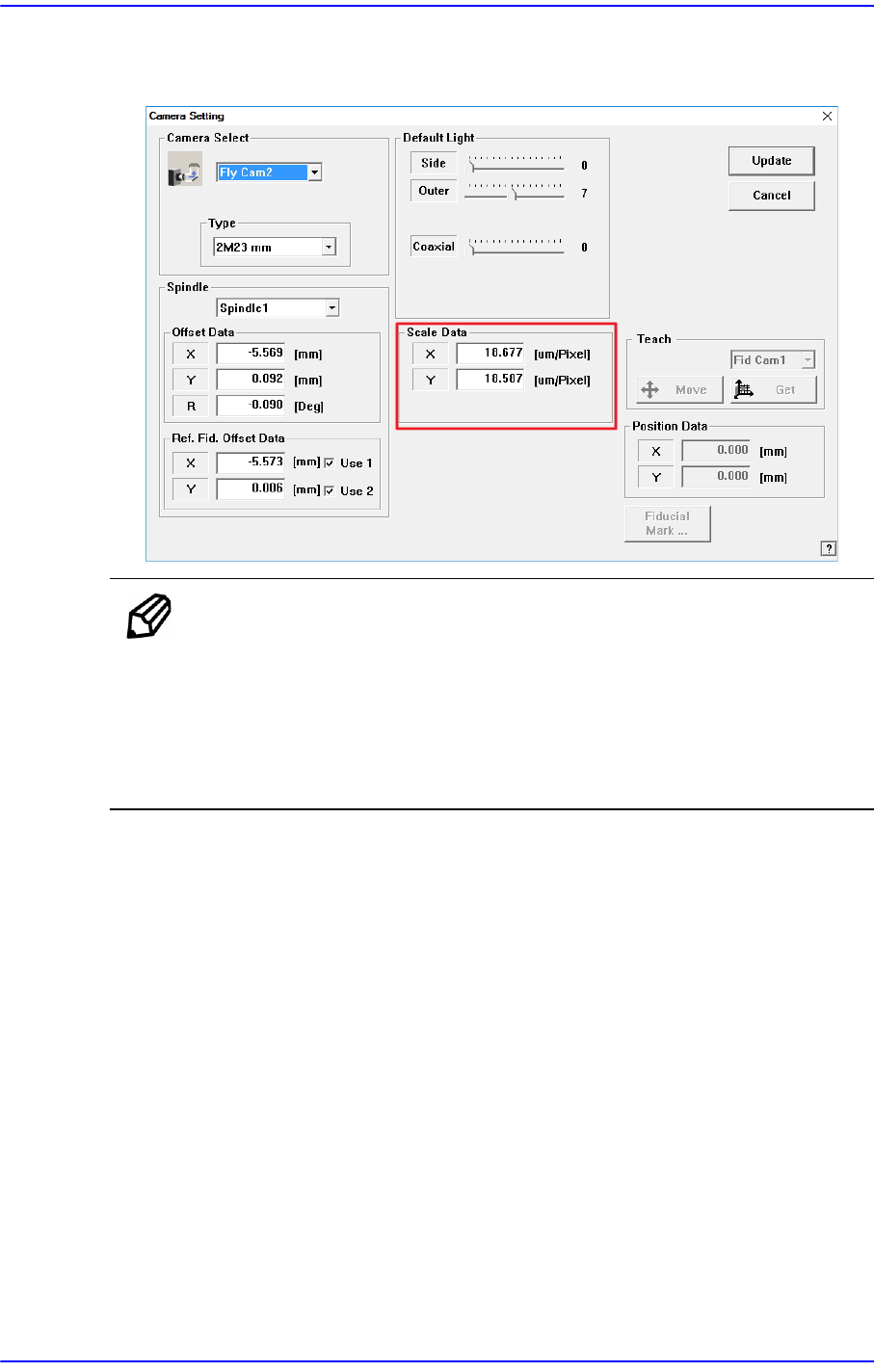
14-69 Machine Calibration 4. If the calibration proced ure is completed for all fly-cameras normally , the result is displayed as shown in the following figure. Click the <Update> button.
14-68
Next Generation, Multi-Functional Placer DECAN S1 Administrator’s Guide
14.3.8.7. Fly Camera Scale Calibration
This calibration is performed to find the scale and rotation offset of the fly-camera. To
perform Fly-Camera Scale Calibration, first confirm that the CNT20 nozzle is installed in
ANC Hole No.1 before operation.
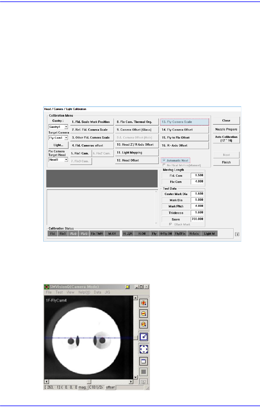
The following is the procedure to calibrate the ‘Fly-Camera Scale Calibration’
1. If the CNT20 nozzle is not installed, click the <Nozzle Prepare> button to manually
insert the CNT20 nozzle into ANC Hole No.1.
2. If the <13 Fly Camera Scale> is clicked after selecting the <Automatic Next> check
box, calibration is performed for the selected gantry automatically.
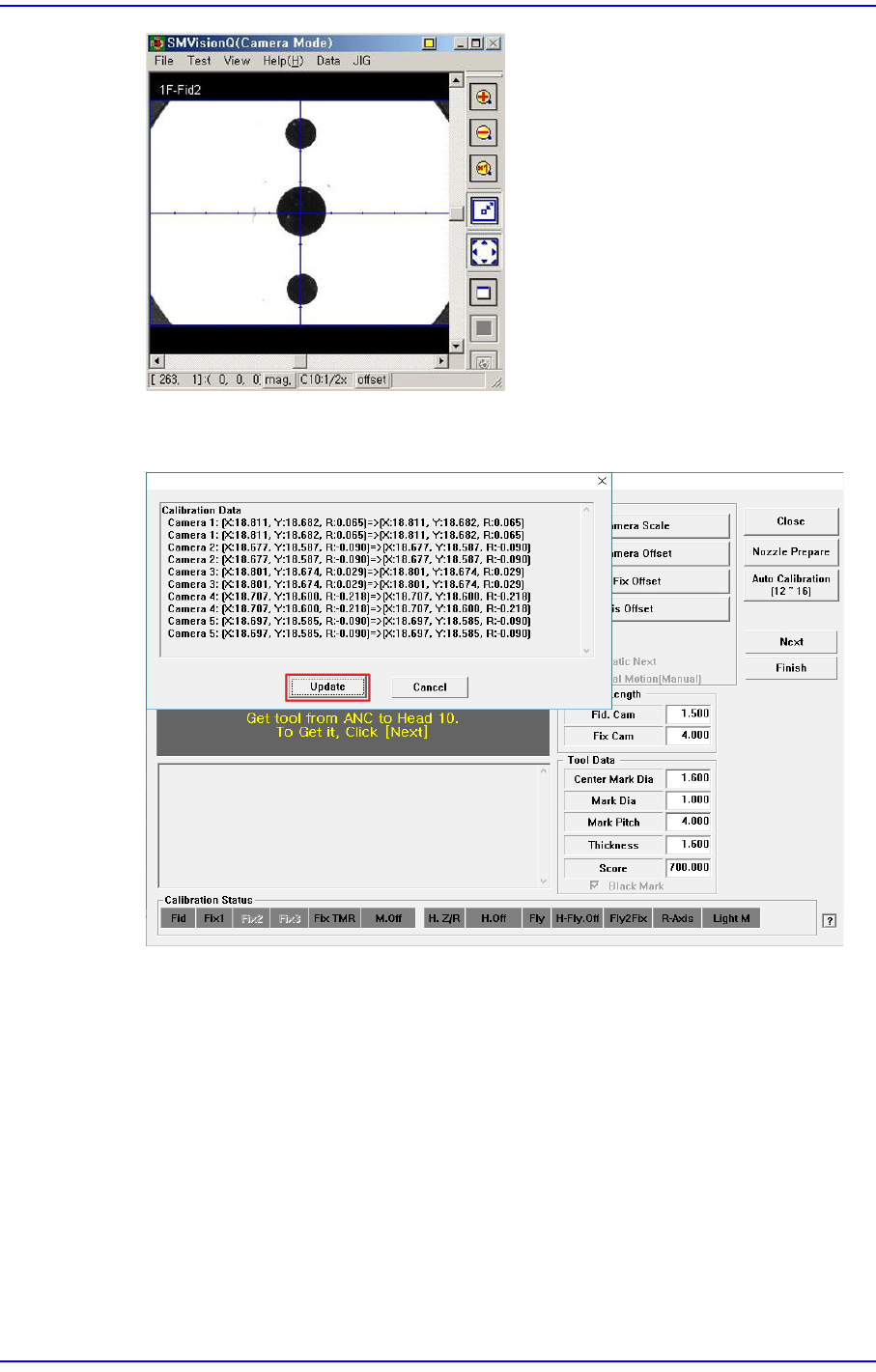
3. In order to perform calibration, recognize the 2 fiducial marks on the bottom surface
of the calibration tool using the fly camera and put the calibration tool on the calibra-
tion tool position on the ANC. Next, recognize the 2 fiducial marks at the edge of the
top surface of the calibration tool.
14-69
Machine Calibration
4. If the calibration procedure is completed for all fly-cameras normally, the result is
displayed as shown in the following figure. Click the <Update> button.
14-70
Next Generation, Multi-Functional Placer DECAN S1 Administrator’s Guide
The result value can be confirmed in the Camera dialog box in the System Setup
menu.
Memo The range of the reference values for the ‘fly-camera calibration’ is as
follows:.
Fly Camera FOV 20.3mm(MEGA) (μm/pixel)
Scale X: 19.22 ~ 20.18
Scale Y: 19.22 ~ 20.18