DECAN_S1_Administrator′s_Guide(Eng_Ver1.5)_Print.pdf - 第487页
15-21 System Setup Select the device to be taught first from <Device> in the <T each> group and insert the CN040 nozzle in the nozzl e holder of the corresponding head. Move the head to th e dripping posi…
15-20
Next Generation, Multi-Functional Placer DECAN S1 Administrator’s Guide
indicated.
The set value can be initialized by the submenu ‘Flux.’ of the ‘Product’ menu.
<Squeeze Warn Count> edit box
This is set for cleaning the flux module during automatic production. If the
corresponding count is reached, the warning message is indicated.
The set value can be initialized by the submenu ‘Flux.’ of the ‘Product’ menu.
<Position> group
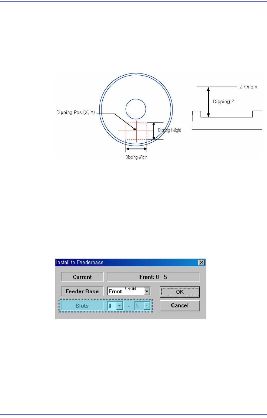
This is enabled when the <Use Flux Device> on the right is selected. Set the dripping
position. If the setup slot is determined at the feeder base of the flux module, the
dripping position is set automatically.
<X> edit box
Refers to the X coordinate of the dripping position.
<Y> edit box
Refers to the Y coordinate of the dripping position.
<Z> edit box
Refers to the Z coordinate of the dripping position.
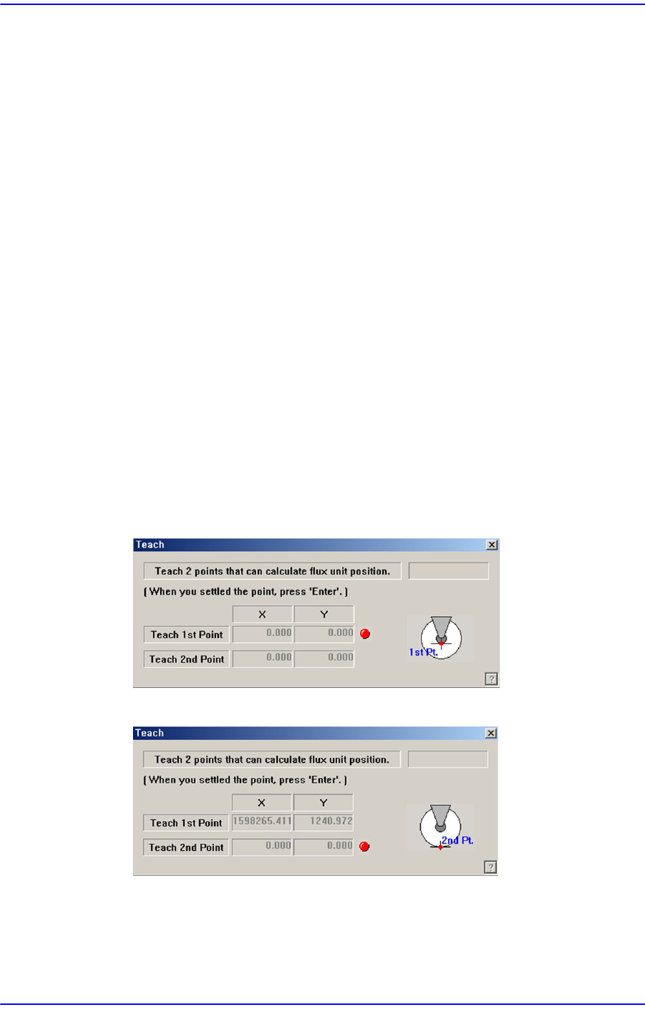
<Teach…X/Y> button
Execute the following dialog box to teach the XY coordinate of the dripping
position.
Set the first point correctly and press the ‘Enter’ key.
Set the second point correctly and press the ‘Enter’ key.
<Teach…[Z]> button
Teach the Z coordinate of the dripping position. The teaching procedure is as
follows:
15-21
System Setup
Select the device to be taught first from <Device> in the <Teach> group and
insert the CN040 nozzle in the nozzle holder of the corresponding head.
Move the head to the dripping position.
Move down the spindle of the head until it contacts the disk surface. If the nozzle
end contacts with the disk surface, the change in the pneumatic pressure
occurs and the Z axis position is taught automatically.
<Use Flux Device> check box
This check box is selected to set the item related to the flux module.
<Churning> button
If this button is selected, the disk of the flux module rotates.
<Not Usable Lane> group
It sets the item related to the operation of the flux module.
<Feeder Base> button
Selects the feeder base on which the flux module is to be installed.
15-22
Next Generation, Multi-Functional Placer DECAN S1 Administrator’s Guide
15.3.4. <LCR Checker> tab screen
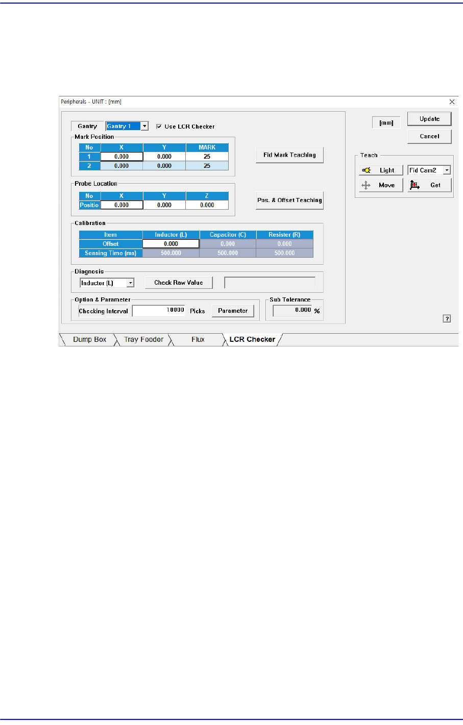
Sets the data related to the LCR Check module. Selecting this dialog box will display the
following dialog box:
Figure15.10 “LCR Checker” tab dialog box
This function prevents mis-insertion of parts by checking if they match the parts to be
produced before putting inductor, capacitor, and resistor parts into production.
To use this function, the LCR Check Module (Meter, Probe, Cable) must be installed in the
equipment.
<Gantry> list box
Select the gantry with the LCR Check module installed.
<Use LCR Checker> check box
It is selected to set LCR Check Module related items.
<Fid Mark Teaching> button
Teaches the fiducial mark of the probe module.
<Mark Postion> group
Displays the fiducial mark position of the probe module.
<Pos. & Offset Teaching> button
Teaches the position of the probe module.
X, Y: Measured values are used.
Z: A fixed valued of -0.3 is entered.