DECAN_S1_Administrator′s_Guide(Eng_Ver1.5)_Print.pdf - 第489页
15-23 System Setup <Probe Location> group Displays the position of the probe module. <Calibration> group The offset and measurement time for LCR parts are corrected. <Diagnosis> group Checks the m…
15-22
Next Generation, Multi-Functional Placer DECAN S1 Administrator’s Guide
15.3.4. <LCR Checker> tab screen
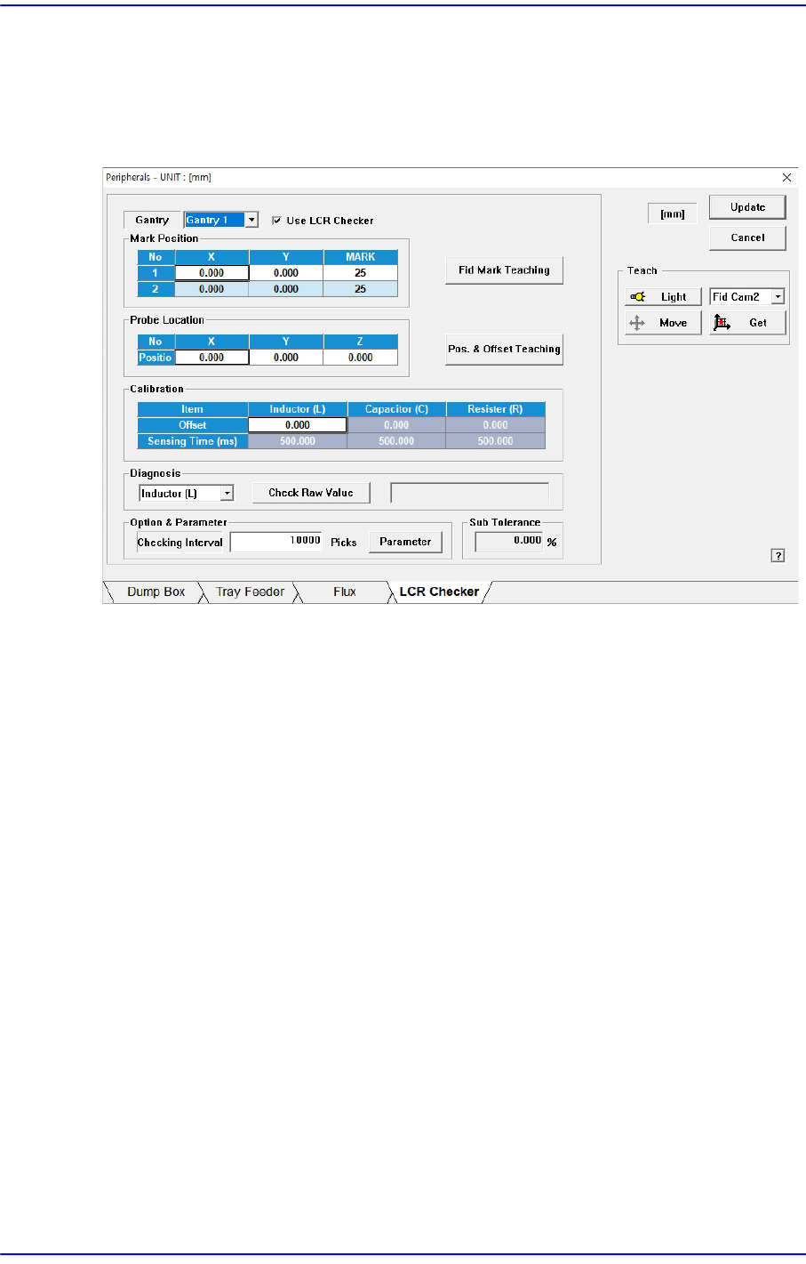
Sets the data related to the LCR Check module. Selecting this dialog box will display the
following dialog box:
Figure15.10 “LCR Checker” tab dialog box
This function prevents mis-insertion of parts by checking if they match the parts to be
produced before putting inductor, capacitor, and resistor parts into production.
To use this function, the LCR Check Module (Meter, Probe, Cable) must be installed in the
equipment.
<Gantry> list box
Select the gantry with the LCR Check module installed.
<Use LCR Checker> check box
It is selected to set LCR Check Module related items.
<Fid Mark Teaching> button
Teaches the fiducial mark of the probe module.
<Mark Postion> group
Displays the fiducial mark position of the probe module.
<Pos. & Offset Teaching> button
Teaches the position of the probe module.
X, Y: Measured values are used.
Z: A fixed valued of -0.3 is entered.
15-23
System Setup
<Probe Location> group
Displays the position of the probe module.
<Calibration> group
The offset and measurement time for LCR parts are corrected.
<Diagnosis> group
Checks the measured values for each LCR part.
<Option & Parameter> group
Sets the interval for LCR inspection during production and inputs the measurement
error for each LCR part.
<Sub Tolerance> group
Enters the measurement error of the part of the LCR Check module.
15-24
Next Generation, Multi-Functional Placer DECAN S1 Administrator’s Guide
15.4. Light [F8]
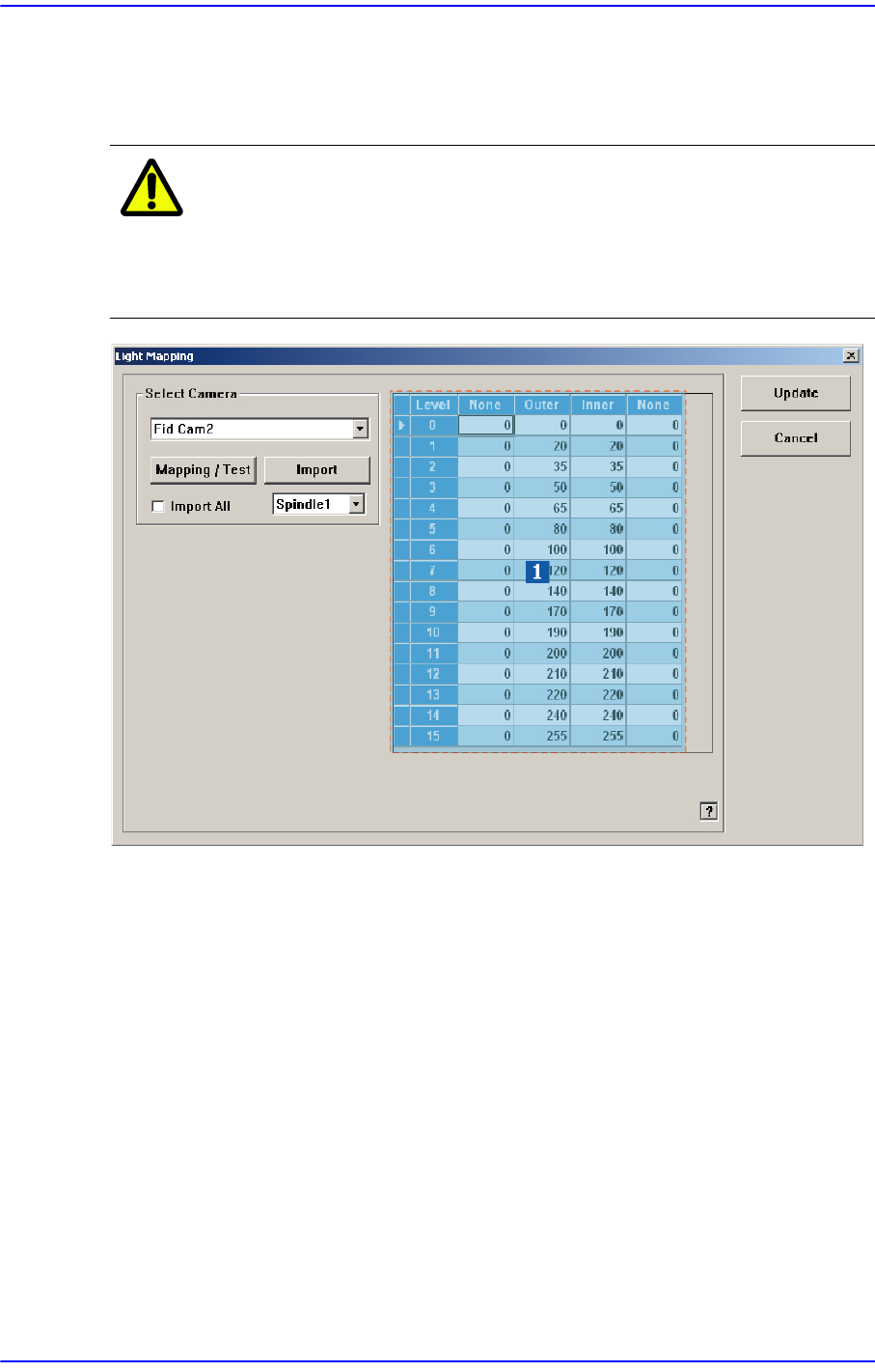
Calibrate the brightness of the light for the camera. In order to perform this calibration,
insert a nozzle for camera test (LightFix) into the ANC.
Caution Since the nozzle for the SM32x,SM411, SM421 model is
not compatible to the one for the light mapping used for the
SM32x,SM411, SM421 model, do not use it for this
machine.
1: Light Level group
<Select Camera> combo box
Selection Control
Select the camera to perform light mapping.
Light Level group
Sets the brightness by light level.
<Level> column
Displays 16 steps of lighting.
<Side> / <Inner> / <Outer>/ <Coaxial> column
For the Fid Camera: Input the side illumination value within the range of 256
values.
For the Fly Camera: Input the side illumination value within the range of 256