DECAN_S1_Administrator′s_Guide(Eng_Ver1.5)_Print.pdf - 第493页
15-27 System Setup <2. Camera> group Selects the camera for performing lig hting brightness test or mapping . Activated cameras can be designated at the sa me time. <3. T ool Setting> group Performs test …
15-26
Next Generation, Multi-Functional Placer DECAN S1 Administrator’s Guide
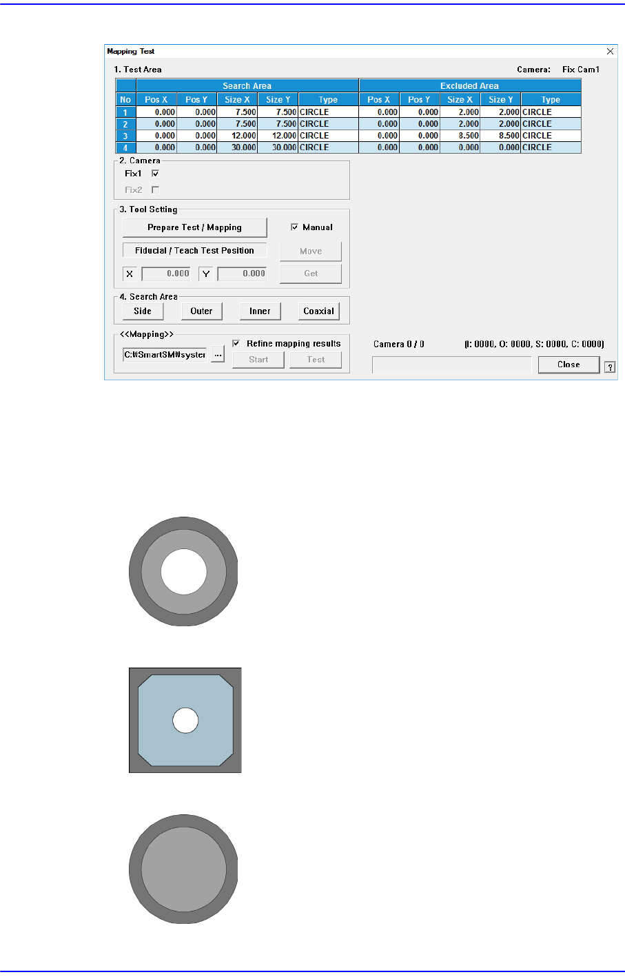
Figure15.13When the Fix Camera is selected
<1. Test Area> group
Designates the area for which the nozzle for test checks the brightness of the
lighting. The are can be designated up to 4. the search area and excluded area are
designated together. The test area is set automatically. Do not change this value.
Figure15.14Bottom Shape of Calibration Nozzle for Fly Camera
Figure15.15Bottom shape of the calibration plate for the Fid camera
Figure15.16Bottom shape of the calibration nozzle for the Fix camera
15-27
System Setup
<2. Camera> group
Selects the camera for performing lighting brightness test or mapping. Activated
cameras can be designated at the same time.
<3. Tool Setting> group
Performs test or preparation for mapping.
<Prepare Test /Mapping> button
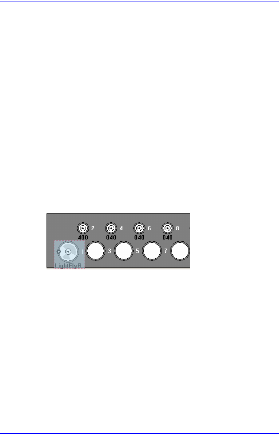
Return all nozzles mounted on the head to each corresponding ANC hole.
Before doing so, arrange the LightFly nozzle, a nozzle for calibration into the
No. 1 hole of the ANC.
If the nozzle arrangement is finished, the <Start> button and <Test> button in
the <Mapping>group.
<4. Search Area> group
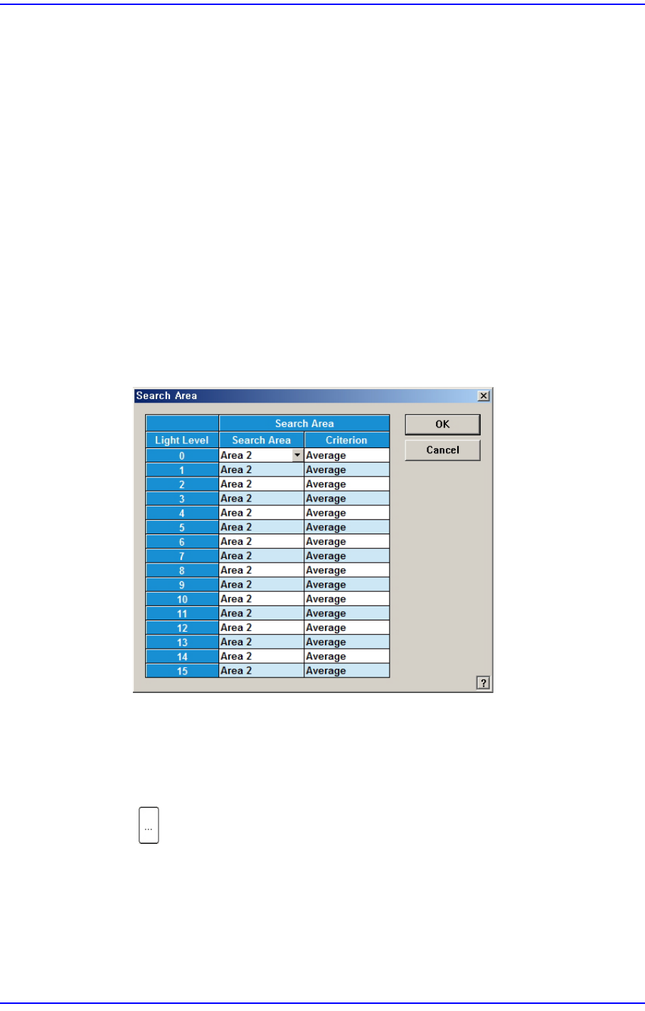
Clicking the button corresponding to the light for which mapping is to be
performed will display the following dialog box.
Click on the button corresponding to the illumination for mapping, set the test area
(Area 1 ~ 4) to 16 illumination levels for each lighting, and setup the average
illumination level for each pixel of the test area to the maximum value.
<Mapping> group
button
Select the Map File to be used for mapping. Since the file name is set
automatically, do not change it.
<Start> button
Start the Mapping.
15-28
Next Generation, Multi-Functional Placer DECAN S1 Administrator’s Guide
<Test> button
Perform test for the mapping result. The light level that does not satisfy the
reference value is searched automatically and it is displayed in the result file.
Perform mapping with the <Refine Mapping Result> check box being selected.
State display
Displays current progressing state.
Camera (Number of camera for which test or mapping is completed) /(Total
number of selected camera)
(I: Inner Level, O: Outer Level, S: Side LevelC: Coaxial Level)
<Close> button
Closes the dialog box.
<Update> button
Transmits the set data to the equipment and closes the dialog box.
<Cancel> button
Ignores the set data and closes the dialog box.
Perform light mapping of the Fly Camera in the following manner:
1. Place the light mapping tool in the No. 1 hole of the ANC.
2. Click the <Light Mapping> button to execute the light mapping dialog box.