DECAN_S1_Administrator′s_Guide(Eng_Ver1.5)_Print.pdf - 第548页
16-2 Next Generation, Multi-Functional Plac er DECAN S1 Administrator’s Guide 16.1. I/O [F2] The <I/O> submenu sets or displays the status of various I/O (input/output) sensors on th e equipment. Figure16. 3 “I/O S…
16-1
Diagnosis
Chapter16. Diagnosis
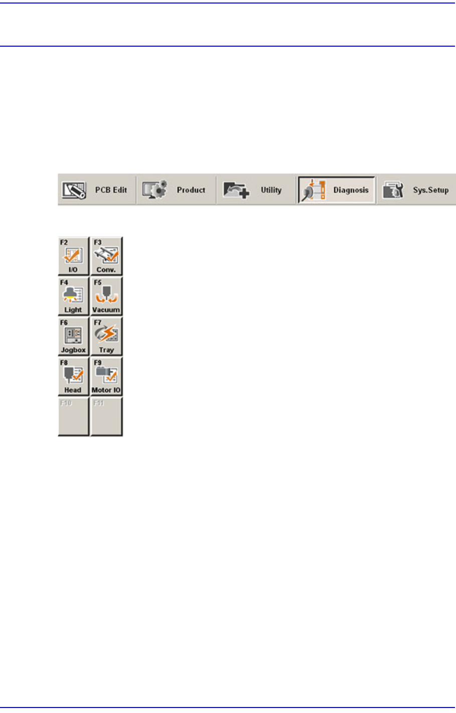
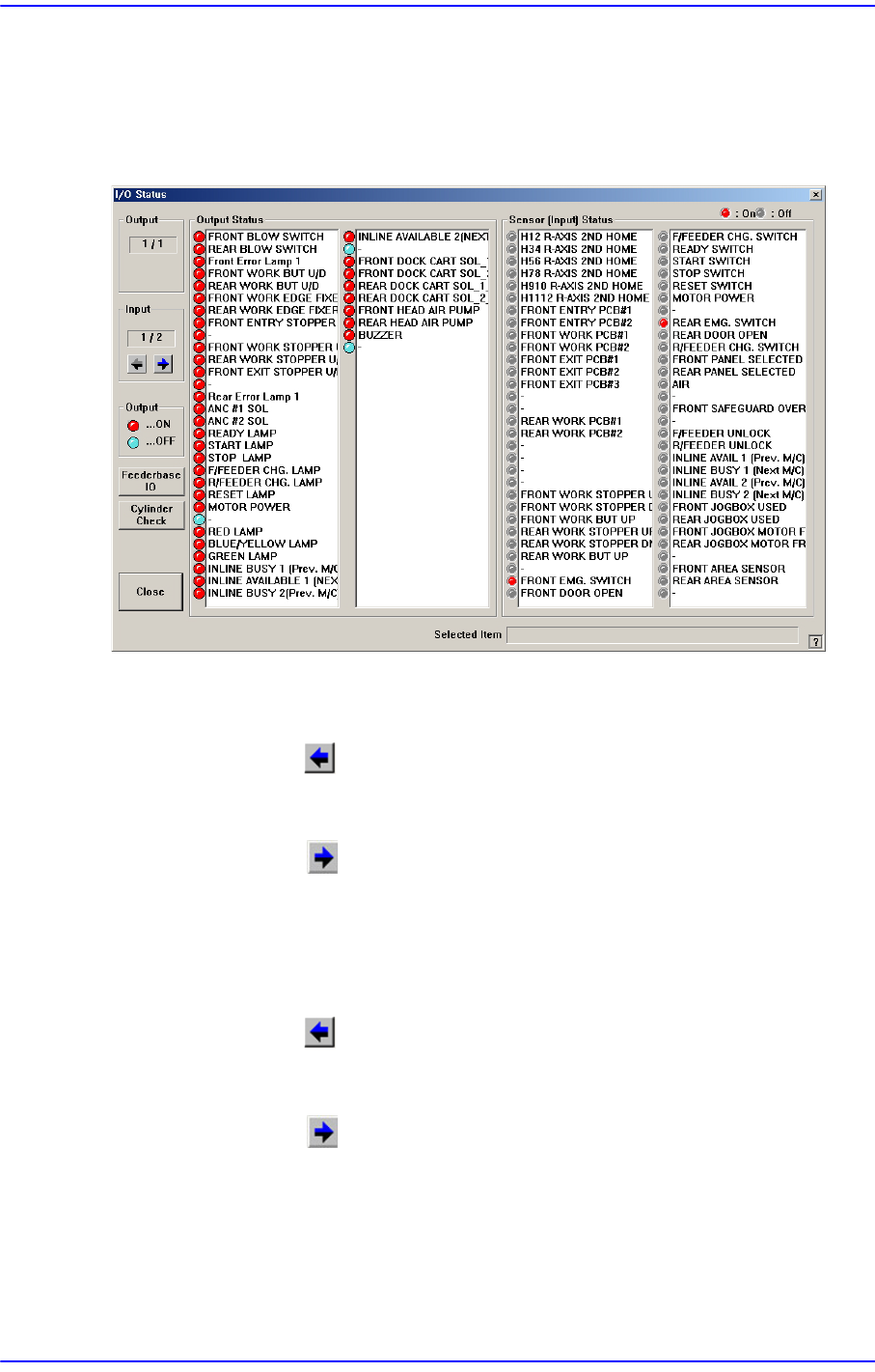
The Diagnosis menu is composed of 6submenus: I/O, Conveyor, Light, Vacuum, Jog box,
Tray, Head, Motor IO. This menu performs a module test on each part.
When a submenu of the <Diagnosis> menu is selected, the corresponding dialog box is
displayed on the screen. While the corresponding dialog box of the submenu is displayed,
selecting the menu again activates the dialog box.
Figure16.1 When the Diagnosis menu is selected
Figure16.2 Submenus of the Diagnosis menu
16-2
Next Generation, Multi-Functional Placer DECAN S1 Administrator’s Guide
16.1. I/O [F2]
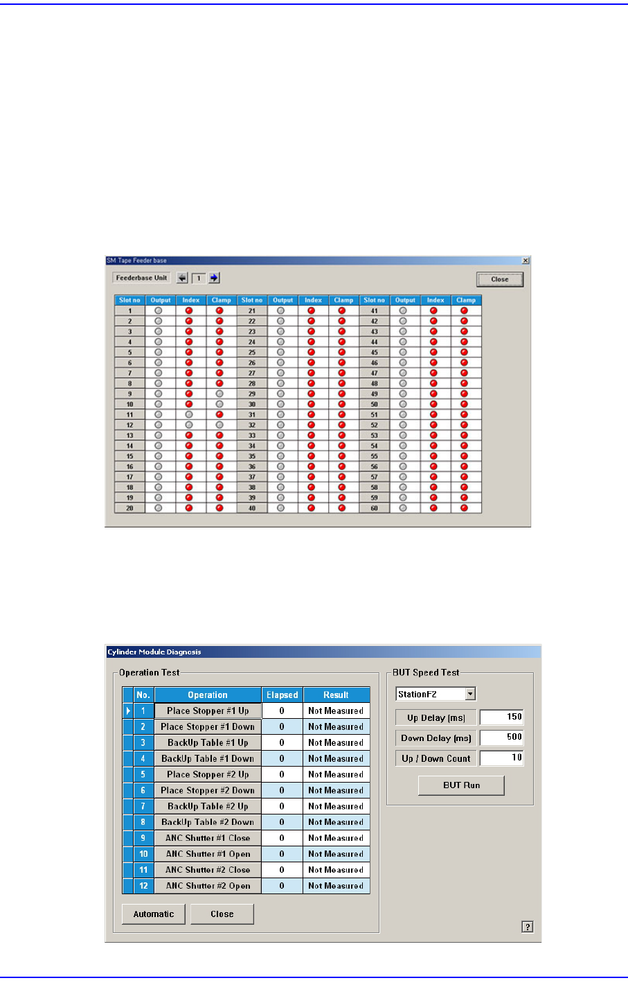
The <I/O> submenu sets or displays the status of various I/O (input/output) sensors on the
equipment.
Figure16.3 “I/O Status “dialog box
<Output> group
Indicates the status of output devices.
<Prev Block> button
Indicates previous output items.
<Next Block> button
Indicates next output items.
<Input> group
Indicates the status of input devices.
<Prev Block> button
Indicates previous input items.
<Next Block> button
Indicates next input items.
<Output Status> group
Indicates the status of the selected output devices. Red indicates on status, and blue
indicates off status.
16-3
Diagnosis
Double clicking the mouse’s left button or pressing the space bar after selecting the
device to be set will allow the output status to be reversed.
<Seneor (Input) Status> group
Indicates the status of the selected input sensor. Red indicates on status, and blue
indicates off status.
<Feederbase I/O> button
The user can confirm if the corresponding feeder is installed in the feeder base slot and
check the feeder output status.
Figure16.4 “SM Tape Feeder base” dialog box
<Cylinder Check> button
Check the state of the cylinder movement. When this button is clicked on, the
following dialog box is displayed.
Figure16.5 “Diagnosis: Cylinder Module Diagnosis” dialog box