DECAN_S1_Administrator′s_Guide(Eng_Ver1.5)_Print.pdf - 第97页
4-15 Tools Shortcut Menu Sends the signal to be ready for rece iving PCBs from the previ ous machine. T o send the signal manually , click on the <Not Busy> button on the right. DI-A vailable (Pre) Receives the s…
4-14
Next Generation, Multi-Functional Placer DECAN S1 Administrator’s Guide
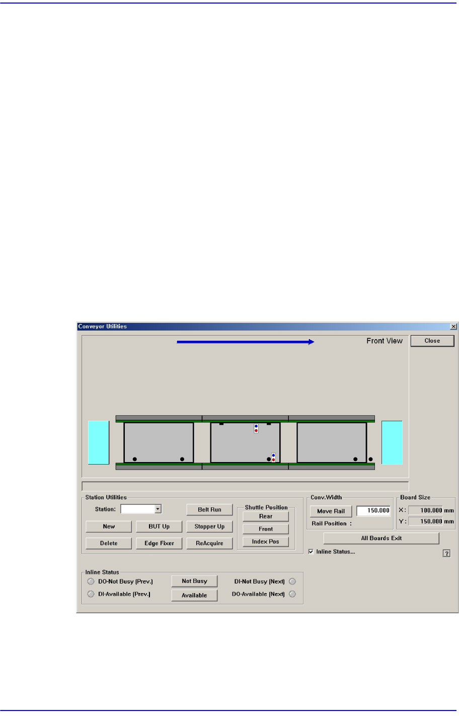
<Index Pos> button: If Exit Shuttle is selected, the corresponding shuttle is
moved to the currently set index position.
The index position can be set in the submenu ‘Calib’ of the ‘System Setup’.
<Conv.Width> group
The width of the conveyor can be adjusted manually.
<Move Rail> button -When the user enters a transport rail width in the edit box
next to this button and click on this button, the transport rail width is adjusted to
the corresponding width.
<Home All> button
Finds the homes of all axes.
<All Board Exit> Button
Discharges all PCBs on the conveyor.
<Inline Status…> check box
The menu that indicates the In-line status of the machine and performs the operation
test of the machine is created.
Figure4.5 “Conveyor System-Inline Status” dialog box
<Inline Status> group
Can handle SMEMA related output manually and display the input status (light
on-On, light off-Off).
DO-Not Busy (Pre.)
4-15
Tools Shortcut Menu
Sends the signal to be ready for receiving PCBs from the previous machine.
To send the signal manually, click on the <Not Busy> button on the right.
DI-Available (Pre)
Receives the signal that the previous machine is ready for sending PCBs.
DI-Not Busy (Next)
Receives the signal that the next machine is ready for receiving PCBs.
DO-Available (Next)
Sends the signal to be ready for sending PCBs to the next machine. To send
the signal manually, click on the <Available> button on the right.
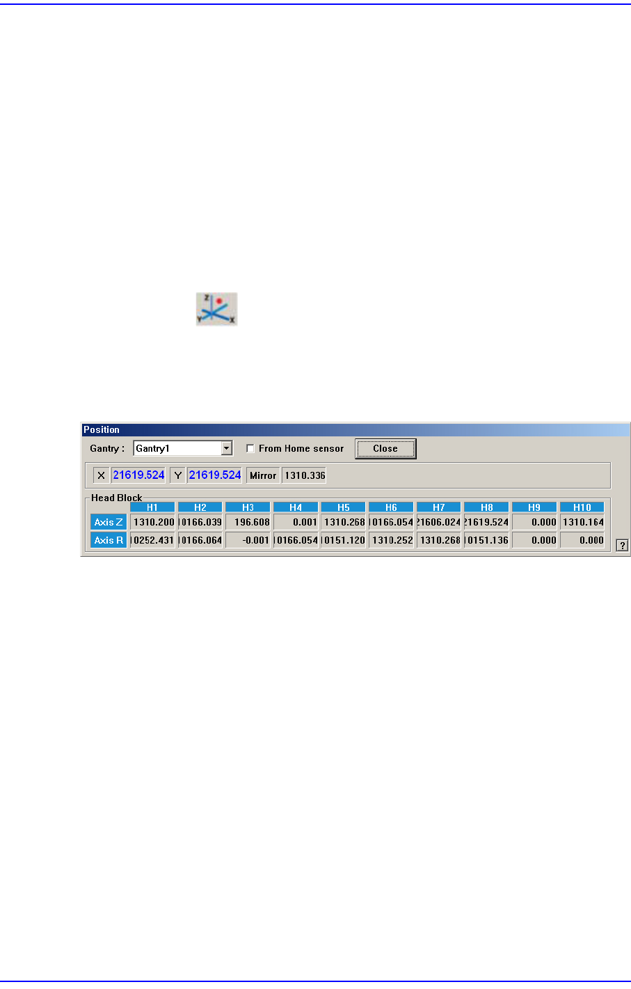
4.6. Current Position
Mainly used when the present coordinates of each driving axis need to be referenced for
teaching or calibration.
Figure4.6 “Position” dialog box
<Gantry> combo box
Select the gantry for which the coordinate is to be checked.
<From Home sensor> check box
This function is used to see how much the nozzle tip of the head has been lowered
from the position of the home sensor for the Z-axis.
Coordinates
X [When 1F-H1 is selected]
Indicates the present position in X direction of Head 1 at the origin of the
equipment.
Y [When 1F-H1 is selected]
Indicates the present position in Y direction of Head 1 at the origin of the
equipment.
Mirror
Indicates the presently rotated angle from the home position of mirror rotation axis
for fly camera.

4-16
Next Generation, Multi-Functional Placer DECAN S1 Administrator’s Guide
Head Block group
Head 1/Axis Z
When the check box for <From home sensor> is not ticked, the height of the
nozzle tip of head 1 on the PCB is indicated.
Head 1/Axis R
Indicates the presently rotated angle from the home position of R axis for head 1.
Head 2/Axis Z
When the check box for <From home sensor> is not ticked, the height of the
nozzle tip of head 2 on the PCB is indicated.
Head 2/Axis R
Indicates the presently rotated angle from the home position of R axis for head 2.
Head 3/Axis Z
When the check box for <From home sensor> is not ticked, the height of the
nozzle tip of head 3 on the PCB is indicated.
Head 3/Axis R
Indicates the presently rotated angle from the home position of R axis for head 3.
Head 4/Axis Z
When the check box for <From home sensor> is not ticked, the height of the
nozzle tip of head 4 on the PCB is indicated.
Head 4/Axis R
Indicates the presently rotated angle from the home position of R axis for head 4.
Head 5/Axis Z
When the check box for <From home sensor> is not ticked, the height of the
nozzle tip of head 5 on the PCB is indicated.
Head 5/Axis R
Indicates the presently rotated angle from the home position of R axis for head 5.
Head 6/Axis Z
When the check box for <From home sensor> is not ticked, the height of the
nozzle tip of head 6 on the PCB is indicated.
Head 6/Axis R
Indicates the presently rotated angle from the home position of R axis for head 6.
Head 7/Axis Z
When the check box for <From home sensor> is not ticked, the height of the
nozzle tip of head 7 on the PCB is indicated.