00197501-02_AI_WPC_Umbau_X-Series_S_DE_EN - 第69页
Review 3 Setting up and Commissioning 3.1 Removing the Standard Component Trolley Feed Device Assembly Instructions / Montageanleitung SIPLACE WPC an SIPLACE X-Serie S SIPLACE WPC on SIPLACE X Series S 03/2020 69 1 1 3 2…
Review
3 Setting up and Commissioning
3.1 Removing the Standard Component Trolley Feed Device
68 Assembly Instructions / Montageanleitung SIPLACE WPC an SIPLACE X-Serie S SIPLACE WPC on SIPLACE X
Series S 03/2020
3.1 Removing the Standard Component Trolley Feed Device
WARNING
Risk of injury when working near the tape cutter.
When working in the area of the tape cutter, move the component trolley out of the machine
and disconnect the machine from the mains supply and the compressed air supply.
► Wait until the operating pressure has dropped to 0 MPa.
► Always secure the machine against unauthorized reactivation.
► Do not reach into the tape cutter.
CAUTION
Risk of injury when performing service work on the tape cutter.
Never support the tape cutter on your body, e.g., on your knees or thighs. Do not place
your feet under the tape cutter.
► Wear appropriately thick protective gloves.
► When removing/fitting the tape cutter, hold it only outside on the left and right.
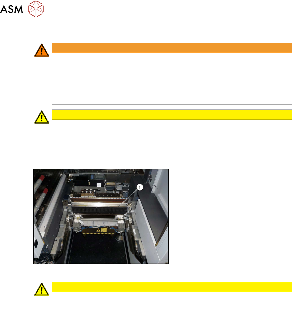
Fig.11: COT insert
1. COT insert
CAUTION
Heavy machine part!
The COT insert is heavy. To lift it out, you will need to use the mounting tool and a suitable
lifting device (hand-operated crane etc.).
Removal
► Switch off the machine, disconnect it from the power supply and secure it to prevent
unauthorized reactivation. See also section 1.2
"Preparatory work..." [}56].
► Dismantle the nozzle changer.
► Disconnect the COT insert from all electrical and pneumatic connections. Mark the positions
of these connections, to make clear assignment easier later on. The connection cables and
hoses are located behind the COT insert – in the space leading to the machine base (under
the nozzle changer). See also the chapter 5.1.3
"Nozzle Changers and Nozzle Stations -
Overview" [}89].
► Dismantle the left side cover. See also the chapter 5.1.4 "Dismantling the Lower Side
Cover" [}91].
► Unhook the middle cover.
Review
3 Setting up and Commissioning
3.1 Removing the Standard Component Trolley Feed Device
Assembly Instructions / Montageanleitung SIPLACE WPC an SIPLACE X-Serie S SIPLACE WPC on SIPLACE X
Series S 03/2020
69
1
1
3
2
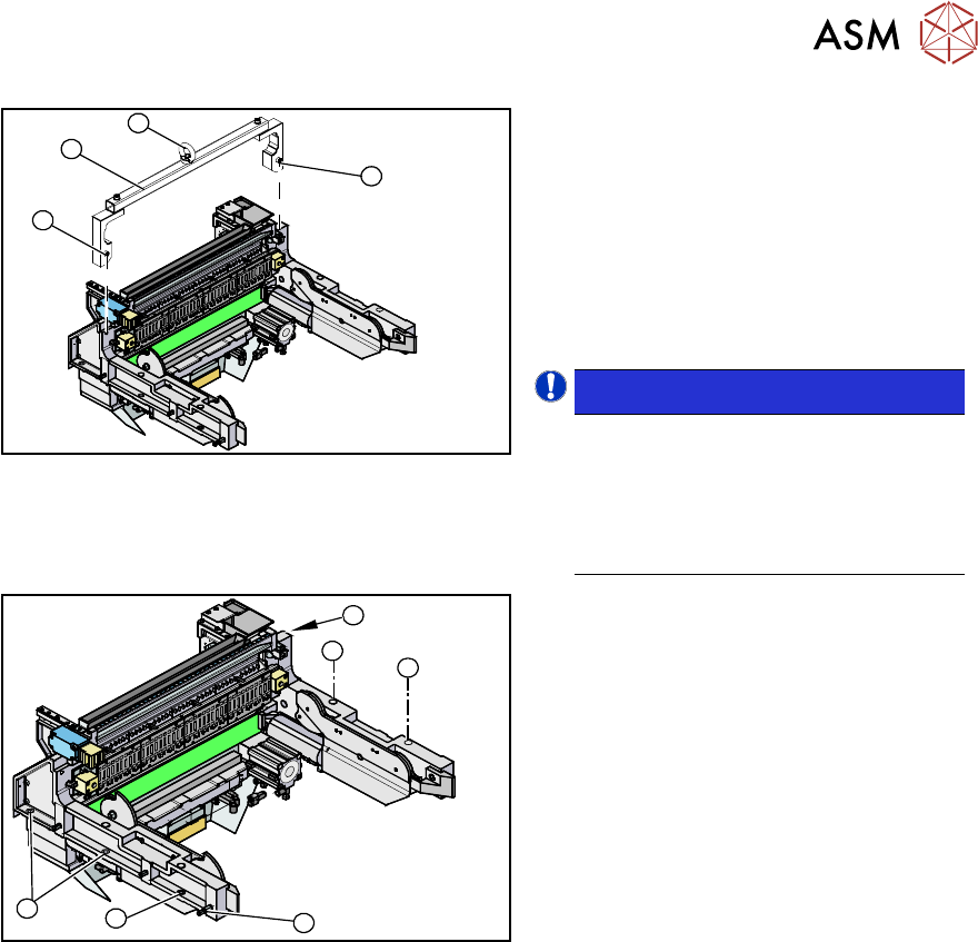
Fig.12: Assembly lifting device and mounting tool
1. Fixtures
2. Mounting tool
3. Eyelet
► Attach the mounting tool (2) to the fix-
tures provided (1)
on the COT insert.
► Fix the lifting device to the eyelet (3) of
the mounting tool (2)
.
NOTICE!
The COT insert can be installed at dif-
ferent positions in the machine loca-
tion. Mark the position of your COT in-
sert, to ensure that this is sub-
sequently returned to its original posi-
tion.
.
1
1
1
1
2
1
Fig.13: Lifting out the COT insert
► Loosen the screws fastening the COT
insert(1)
.
► Lift the complete COT insert out of the
machine and place it on a suitable sur-
face (four wooden blocks etc.).
► Make sure that you do not damage any
valves, connection cables, hoses etc.
Review
3 Setting up and Commissioning
3.2 Installing the Manual Table
70 Assembly Instructions / Montageanleitung SIPLACE WPC an SIPLACE X-Serie S SIPLACE WPC on SIPLACE X
Series S 03/2020
3.2 Installing the Manual Table
NOTICE
Cables and hoses
► Before installing the table ensure to route all cables and hoses for the subsequent
connection.
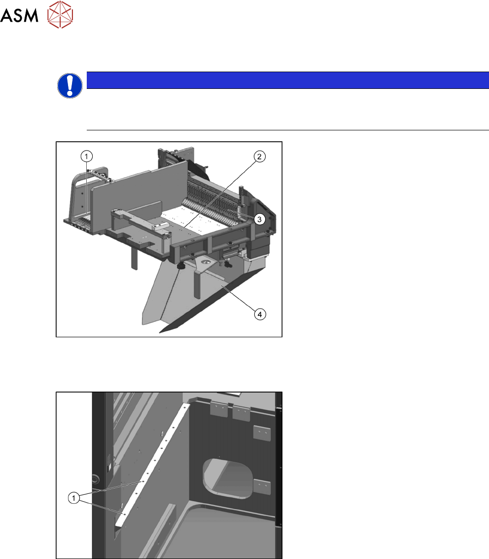
Fig.14: Manual table
1. Free tracks for tape reel container
assembly /WPC [03060460-xx]
2. Insertion for the SIPLACE WPC5/
WPC6
3. FCU
4. Waste slide, welded WPC / JTF
[03111440-xx]
► Before installing the fixed table, the waste slide must be removed. See also the chapter 3.5
"Fitting the Waste Tape Slide" [}77].
Fig.15: Installation position 3
The fixed table for the SIPLACE WPC5/
WPC6 is fitted to the outermost position of
the SIPLACE X-Series S.
1. Installation position 3