00197501-02_AI_WPC_Umbau_X-Series_S_DE_EN - 第82页
Review 4 Operator Tasks 4.1 Docking the SIPLACE WPC5/WPC6 82 Assembly Instructions / Montageanleitung SIPLACE WPC an SIPLACE X-Serie S SIPLACE WPC on SIPLACE X Series S 03/2020 Setting the exact height of the SIPLACE WPC…
Review
4 Operator Tasks
4.1 Docking the SIPLACE WPC5/WPC6
Assembly Instructions / Montageanleitung SIPLACE WPC an SIPLACE X-Serie S SIPLACE WPC on SIPLACE X
Series S 03/2020
81
4 Operator Tasks
4.1 Docking the SIPLACE WPC5/WPC6
When installing and removing the SIPLACE WPC5/WPC6, make sure that the arms of the feed
axis do not hit any parts (e.g. stationary cameras etc.).
► If the SIPLACE WPC5/WPC6 is not yet standing on its wheels, fasten the hexagonal shaft (crank
handle) to the lifting mechanism and turn in a clockwise direction, to lift the WPC5/WPC6.
► Stop turning when you have enough room to dock the SIPLACE WPC5/WPC6 onto the machine.
► Open the machine cover on the relevant location.
► If there is a height limiter present in the SIPLACE WPC5/WPC6 location, this needs to be
turned over and fixed into place upside down. Make sure that the height limiter does not touch
the cover plate. To do this, remove the three screws fastening the height limiter and fit it into
the same place upside down (with two fastening screws).
► Move the SIPLACE WPC5/WPC6 into the location and connect the energy and data supply
cable. Make sure that the arms of the feed axis do not collide with any machine parts.
► Connect the SIPLACE WPC5/WPC6 safety chain to the machine.
► Lower the SIPLACE WPC5/WPC6 until it is standing on its feet. Turn the crank handle on the
lifting mechanism until the wheels are about 1 cm above the ground.
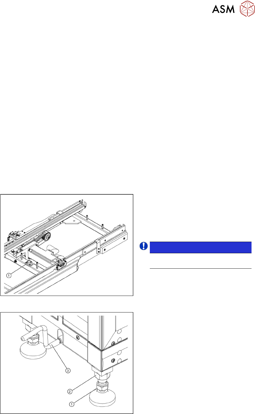
Aligning the SIPLACE WPC5/WPC6
Fig.37: Circular spirit level
1. Circular spirit level
► Check the position of the SIPLACE
WPC5/WPC6 with the help of the integ-
rated spirit level (1)
, which is between
the two rails of the feeder axis.
NOTICE!
The cover on the feed axis arms is not
shown in the diagram.
.
Fig.38: Setting the adjustable feet
1. Foot with 30 mm nut
2. 36 mm locknut
3. Hexagonal shaft (crank handle)
► If the SIPLACE WPC5/WPC6 is not
level, use a 30 mm and 36 mm open-
ended wrench to adjust the feet in turn,
until more than half of the bubble is in
the circle of the spirit level.
Review
4 Operator Tasks
4.1 Docking the SIPLACE WPC5/WPC6
82 Assembly Instructions / Montageanleitung SIPLACE WPC an SIPLACE X-Serie S SIPLACE WPC on SIPLACE X
Series S 03/2020
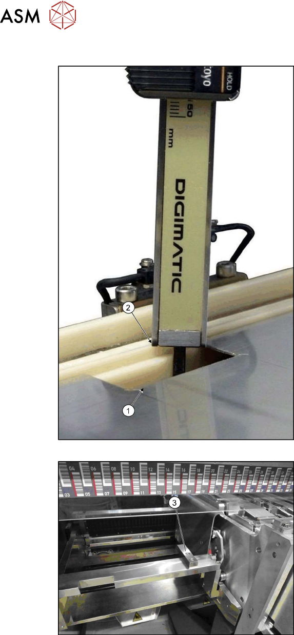
Setting the exact height of the SIPLACE WPC5/WPC6
Fig.39: Measurement with sliding gauge
Fig.40: Aluminum block on component trolley
► Use a measuring scale to adjust the
SIPLACE WPC5/WPC6 to the correct
height through the opening (1)
on the
cover plate of the feed axis.
► Use the gauge to measure the height of
the SIPLACE WPC5/WPC6 from the
white sliding surface of the waffle pack
tray carrier (2) to the aluminum block
on the component trolley docking unit.
(3). The correct height should be
87±0.5mm.
► If the height is outside the specified
value, adjust each foot accordingly to
lower or raise the SIPLACE WPC5/
WPC6 to the correct height.

Review
4 Operator Tasks
4.2 Undocking the SIPLACE WPC5/WPC6
Assembly Instructions / Montageanleitung SIPLACE WPC an SIPLACE X-Serie S SIPLACE WPC on SIPLACE X
Series S 03/2020
83
4.2 Undocking the SIPLACE WPC5/WPC6
Preparatory work
► Go to Manual operations => Entire machine functions and perform a Overall reference
run.
► Perform a SIPLACE WPC reference run. To do this, select Manual operations => Subsys-
tems => WPC and click on Reference run.
► Use the software to move the lifting axis of the SIPLACE WPC5/WPC6 into the transport posi-
tion. To do this, select the Move into transport position
button. The SIPLACE WPC5/WPC6
will be moved to a defined position, from which it can be safely transported.
► Disconnect the SIPLACE WPC5/WPC6 from the power supply and the data supply.
Removing the SIPLACE WPC5/WPC6
► Open the machine covers on the relevant changeover table.
► Move the changeover table out of the machine.
► Fasten the hexagonal shaft (crank handle) to the lifting mechanism of the SIPLACE WPC and
turn in a clockwise direction, to lift the SIPLACE WPC5/WPC6.
► Stop turning as soon as you have enough room to undock the SIPLACE WPC5/WPC6 from
the machine. Make sure that the feeder mechanism does not get caught anywhere!
► Remove the SIPLACE WPC5/WPC6.
Transporting the SIPLACE WPC5
► When the lifting axis is in its lowermost position (transport position), the SIPLACE WPC5/
WPC6 can be moved on a level floor.
► To transport on the hand lift, ALWAYS turn the carriage COMPLETELY up. If you do not, the
weight of the SIPLACE WPC will burden the lifting spindle of the carriage and the spindle
could be bent.