00197501-02_AI_WPC_Umbau_X-Series_S_DE_EN - 第86页
Review 4 Operator Tasks 4.3 Automatic Calibration 86 Assembly Instructions / Montageanleitung SIPLACE WPC an SIPLACE X-Serie S SIPLACE WPC on SIPLACE X Series S 03/2020 Fig.47: Accept ► After successful calibration, the…
Review
4 Operator Tasks
4.3 Automatic Calibration
Assembly Instructions / Montageanleitung SIPLACE WPC an SIPLACE X-Serie S SIPLACE WPC on SIPLACE X
Series S 03/2020
85
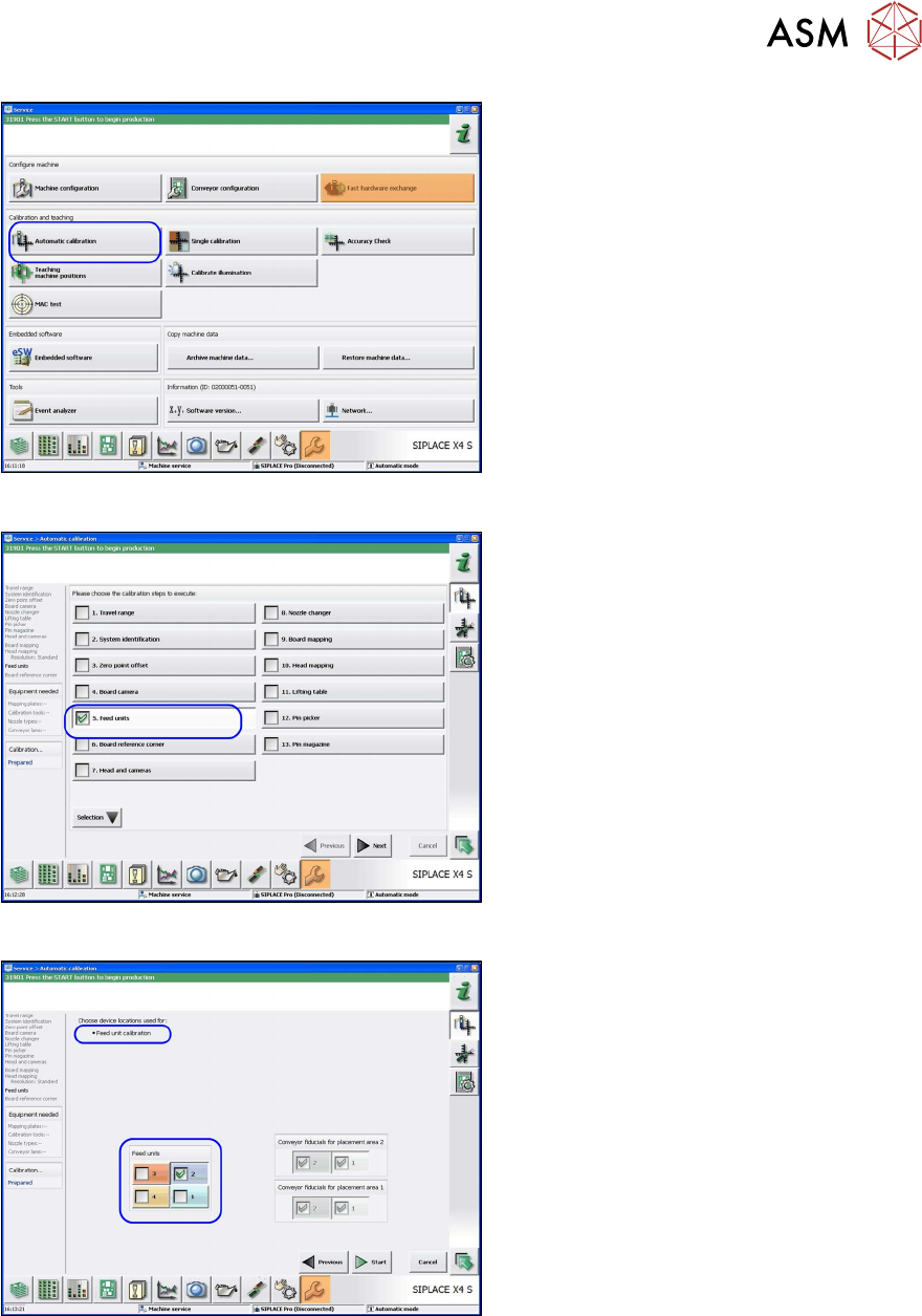
Fig.44: Automatic calibration
► In the Station Software view, click on
Service
, Configure Machine and se-
lect Automatic Calibration
.
ð The Automatic Calibration view
will be shown.
Fig.45: Automatic calibration: feed units
► Go to the Automatic Calibration view
and select the calibration step Feed
units.
► Click Next.
ð The Feed unit calibration view will
open.
Fig.46: Feed unit calibration
► Go to the Feed unit calibration view
and select the feeder unit at location 2.
► Click on Start.
Review
4 Operator Tasks
4.3 Automatic Calibration
86 Assembly Instructions / Montageanleitung SIPLACE WPC an SIPLACE X-Serie S SIPLACE WPC on SIPLACE X
Series S 03/2020
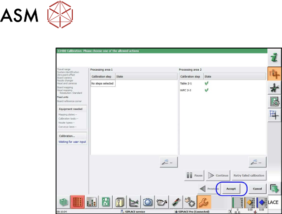
Fig.47: Accept
► After successful calibration, the X table
will be shown at location 2. Click on
Apply
.
ð Calibration has finished.
Review
5 Appendix
5.1 Excerpts from the Service Manual
Assembly Instructions / Montageanleitung SIPLACE WPC an SIPLACE X-Serie S SIPLACE WPC on SIPLACE X
Series S 03/2020
87
5 Appendix
5.1 Excerpts from the Service Manual
The following chapters are excerpts from the service manual for your machine. If required, further
information is provided there.
●
Service manual "SIPLACE X-Series S" [DE:00197041-xx] [EN:00197042‑xx]
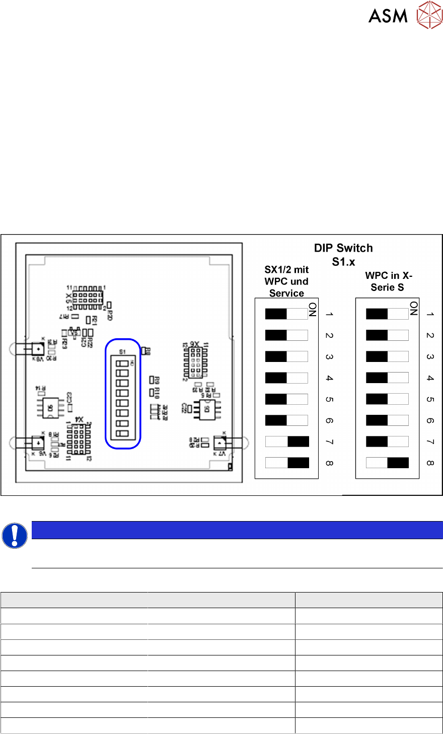
5.1.1 Setting the DIP Switch on the CAN Switch
► Disconnect the CAN switch from the voltage supply.
► Remove the two screws fastening the upper section (side with label) and remove this upper
section.
► Set the DIP switches:
Fig.48: Board in CAN switch
NOTICE
Default setting
The CAN switch is preset as a default for the SIPLACE X-Series S.
DIP switch S1 in CAN switch [03083844-xx]
DIP switch S1 ON OFF
S1.1 Test mode Normal mode
S1.2 500 kBaud 1 MBaud
S1.3 See table below See table below
S1.4 See table below See table below
S1.5 See table below See table below
S1.6 ASC Test ON ASC Test OFF
S1.7 120 Ohm CAN 1 No terminal resistor
S1.8 120 Ohm CAN 2 No terminal resistor