00197501-02_AI_WPC_Umbau_X-Series_S_DE_EN - 第89页
Review 5 Appendix 5.1 Excerpts from the Service Manual Assembly Instructions / Montageanleitung SIPLACE WPC an SIPLACE X-Serie S SIPLACE WPC on SIPLACE X Series S 03/2020 89 Description of CAN node NC tape cutter module …
Review
5 Appendix
5.1 Excerpts from the Service Manual
88 Assembly Instructions / Montageanleitung SIPLACE WPC an SIPLACE X-Serie S SIPLACE WPC on SIPLACE X
Series S 03/2020
The DIP switch setting S1.3 to S1.5 is used to configure the display (LED) i.e the number of error
frames needed for the LED to change its status from green to red. The default setting is that the
LED turns red for each error frame received.
LED status error frames
LED status S1.3 S1.4 S1.5
1 error frame OFF OFF OFF
5 error frames/minute ON OFF OFF
10 error frames/minute OFF ON OFF
10 error frames/hour ON ON OFF
50 error frames/hour OFF OFF ON
100 error frames/hour ON OFF ON
500 error frames/hour OFF ON ON
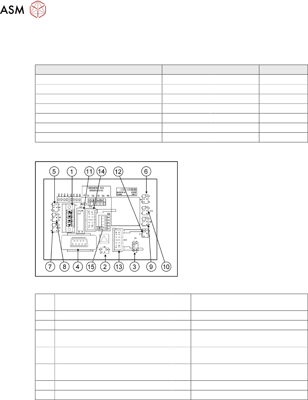
5.1.2 Control Unit on Cutter (CAN Nodes)
Fig.49: CAN node NC tape cutter module
With the CAN node module, a new controller
[03052927-xx] has been developed for the
SIPLACEX4I, HF, D3 and X series ma-
chines. This controls both the cutter and the
nozzle changer of the respective location. If
this control unit is installed in older ma-
chines, you will also need to use the relev-
ant CAN bus address jumper for your
machine's installation site.
1 1X1 – Energy supply with automatic
CAN ID
2 X2 – Energy supply, tape cutter +24V/
+5V
3 X3 – Reject bin (nozzles, components) 4 X4 – CAN bus connection
5 X5 – Energy supply to valve (left) 6 X6 – Energy supply to valve (right)
7 X7 – Proximity switch for stroke cylinder
out (left)
8 X8 – Proximity switch for stroke cylinder
in (left)
9 X9 – Proximity switch for stroke cylinder
out (right)
10 X10 – Proximity switch for stroke cylinder
in (right)
11 X11– Test connector, tape cutter 12 X12 – Compressed air valve (additional
pneumatic unit for rejecting components)
13 X13 – Nozzle changer, row 1 14 X14 – Nozzle changer, row 2
15 DIP switch group S3 (see below)
Review
5 Appendix
5.1 Excerpts from the Service Manual
Assembly Instructions / Montageanleitung SIPLACE WPC an SIPLACE X-Serie S SIPLACE WPC on SIPLACE X
Series S 03/2020
89
Description of CAN node NC tape cutter module
This board is backwards compatible to the old tape cutter board. It can be used at X, HF and D
series machines.
The CAN processor decides which functions need to be checked at the individual locations, de-
pending on the cables connected and the type of DIP switched set.
DIP switch group S3 - overview
DIP
switch
DIP switch meaning
1 ON: Setting the CAN ID via DIP switch 2 and 3 – OFF: Cable Select
2 CAN -ID 0 ON: Gantry 1
1)
ON
OFF: Gantry 2
1)
ON
ON: Gantry 3
1)
OFF
OFF: Gantry 4
1)
OFF: Cable select
3 CAN - ID 1
4 ON: Only tape cutter – OFF: Nozzle changer and tape cutter
2)
5 ON: Module in reset-mode – OFF: Module in standard mode
1)
Not all gantries may be available, depending on the machine type.
2)
Even if there is no nozzle changer installed and only the tape cutter needs to be controlled, this
switch still needs to be set to OFF for the reject bin query and the reject station.
X series machine with CAN node
The cable of the machine (cable harness machine) has to be by-passed as shown in the list:
*112: Gantry 1: 10/11/12 by-passed
*122: Gantry 2: 11/12 by-passed
*132: Gantry 3: 10/12 by-passed
*142: Gantry 4: not by-passed
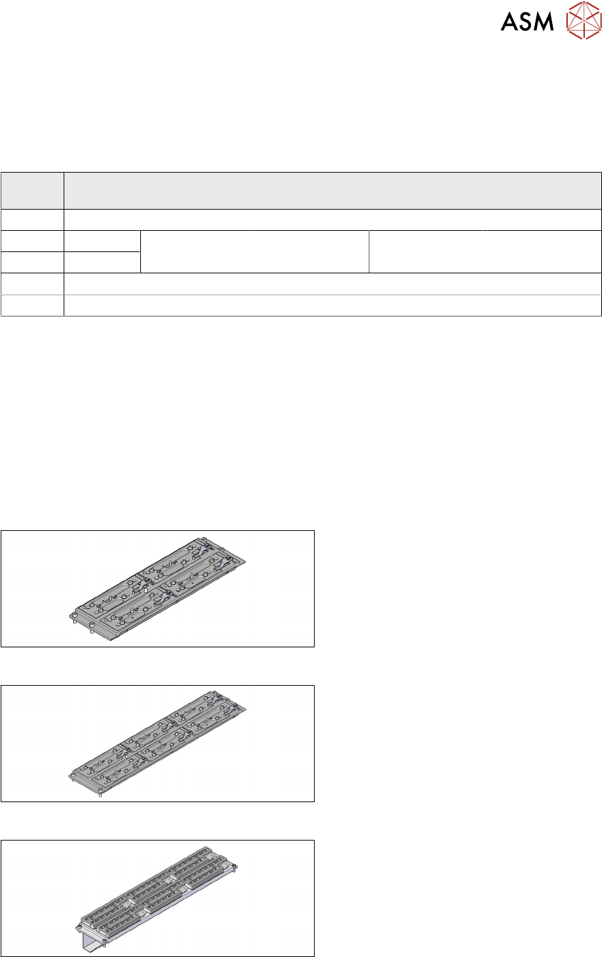
5.1.3 Nozzle Changers and Nozzle Stations - Overview
Fig.50: Nozzle changer short [03103649‑xx]
Standard nozzle changer, short
[03103649‑xx] for four magazines
Fig.51: Nozzle changer, long [03147324‑xx]
Standard nozzle changer, long
[03147324‑xx] for six magazines
Fig.52: Nozzle changer, long
Nozzle changer, long
for SIPLACE C&P20 [03070123‑xx]
for SIPLACE C&P20M [03147324‑xx]
with six magazines [00119715‑xx]
Review
5 Appendix
5.1 Excerpts from the Service Manual
90 Assembly Instructions / Montageanleitung SIPLACE WPC an SIPLACE X-Serie S SIPLACE WPC on SIPLACE X
Series S 03/2020
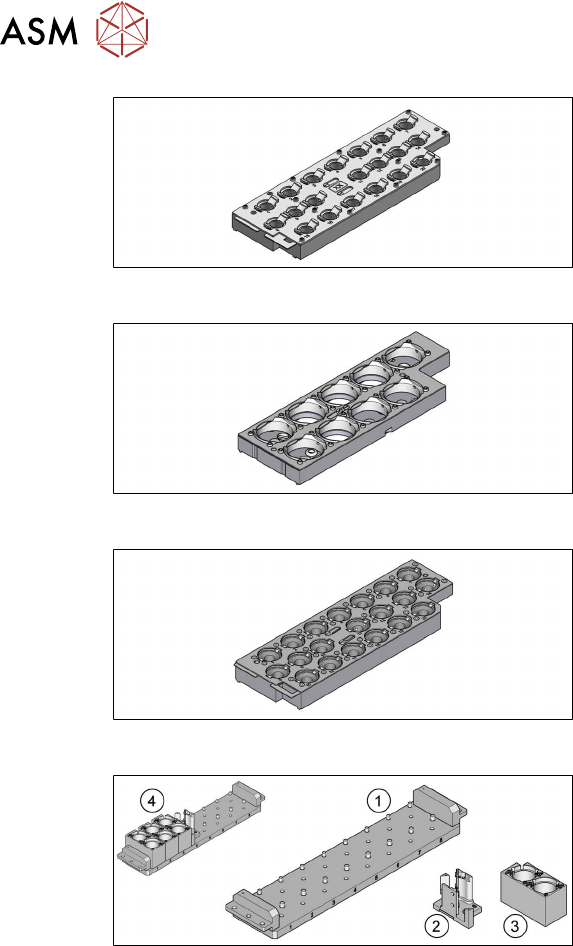
Fig.53: Magazine 20xx [03135469-xx]
Magazine for 20 nozzles of 20xx series
With two fiducials [03135469‑xx]
With three fiducials [03226630‑xx]
Fig.54: Magazine 28xx [03065782-xx]
Magazine for nozzles of 28 xx series
Fig.55: 40xx/60xx magazine [03101503-xx]
Magazine for nozzles of 40xx/60xx series
With two fiducials [03101503‑xx]
With three fiducials [03218226‑xx]
Fig.56: Nozzle changer TwinStar (short) [03062452‑xx]
1. Nozzle changer TwinStar (short)
[03062452‑xx]
2. Magazine for 1 nozzle [03001807-xx]
3. Magazine for 2 nozzles [03005191-xx]
4. Nozzle changer in standard configura-
tion
1x magazine for 1 nozzle
3x magazine for 2 nozzles