TR7500_Hardware_ch - 第25页
24 步驟 6 : 點 擊 選 單中的圖示 ( D o w n l o a d t o P L C) , 點 選是 , 確 認 覆蓋 現 有的程式,如下圖所示 : 步驟 7 : 等 候 PC 傳輸 資料 至 P LC 後,程式 即 可 更 新 完成。 1 .6 P LC 硬體簡介 1 . 6 .1 C P U ( F P2 - C1) 單元 1 . 6 . 1 .1 S t a t u s i n d i ca t o r LE D s…
23
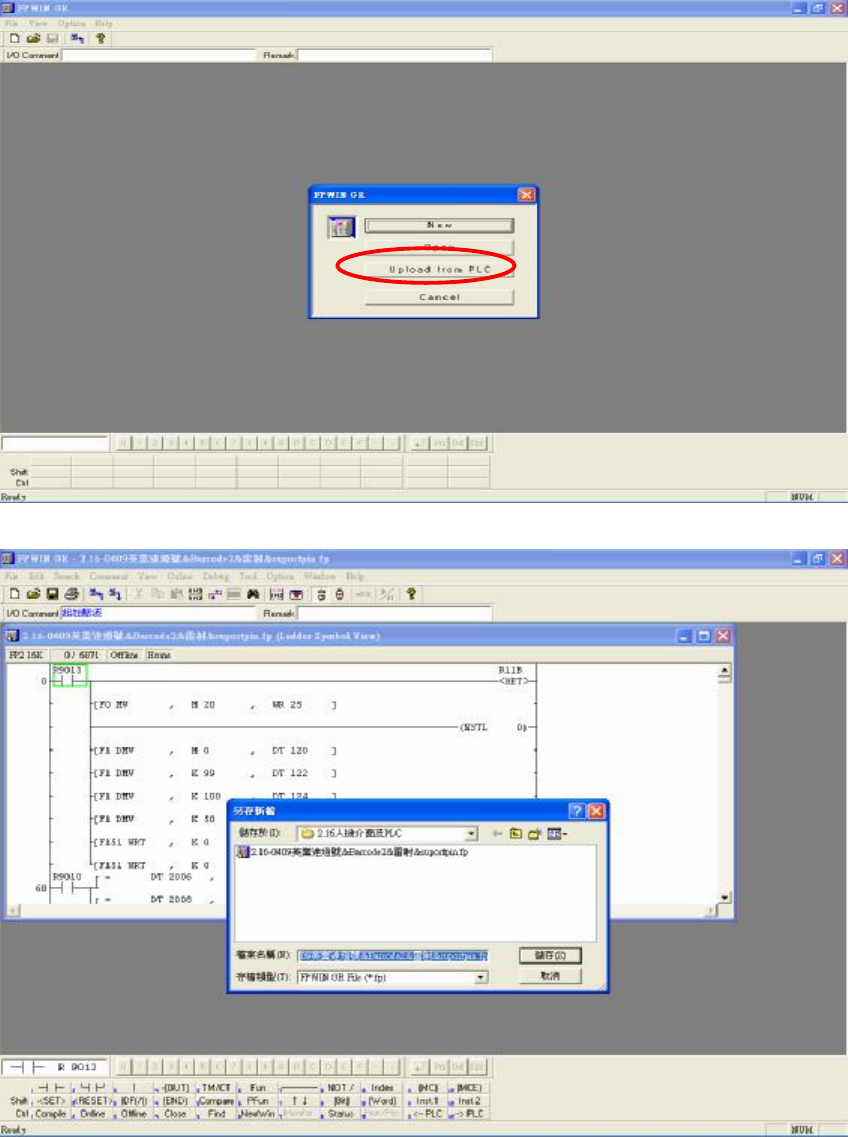
步驟1:先將 PLC-PC 傳輸線連接好,PS2 端連接人機介面後方,RS232 連接 Main PC COM1。
步驟2:開啟程式集中的 FPWIN GR。
步驟3:進入 FPWIN GR 軟體程式,如下圖所示,點選 Upload from PLC(讀取 PLC 的資料):
步驟4:讀取後,點擊 File 選擇 Save as,把原先舊檔案先備份儲存,如下圖所示:
步驟5:備 份 後,將 原 本 的 PLC 程式關閉,再點擊 File 選擇 Open 開啟欲更新的人機介面程式( *.fp),
如下圖所示:
24
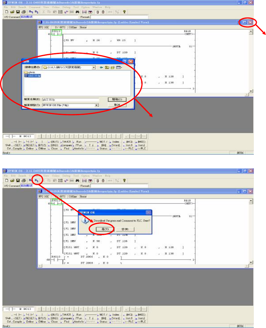
步驟6:點擊選單中的圖示 (Download to PLC),點選是,確認覆蓋現有的程式,如下圖所示:
步驟7:等候 PC 傳輸資料至 PLC 後,程式即可更新完成。
1.6 PLC 硬體簡介
1.6.1 CPU(FP2-C1)單元
1.6.1.1 Status indicator LEDs
CLOSE
選擇欲更新的程式檔案( *.fp)

25
LED Description
RUN (green) This lights in the RUN mode, to indicate that the program is begin
executed. It flashes during forced input/output.
PROG. (green) This lights in the PROG. mode. Operation stops while this LED is
lighted. It flashes when waiting for connection of slave station on
remote I/O system. If the memory is initialized, the brightness dims,
indicating that initialization is being executed.
TEST (green) This lights in the test operation mode.
BREAK (green)
This lights in the operation halts at a break during a test run or halts
during the step operation mode for the test run.
ERROR (red) This lights if an error is detected during the self-diagnostic function.
BATT. (red) This lights when the voltage of the backup battery drops below a
specific value.
ALARM (red) This lights if a hardware error occurs, or if operation slows because
of the program, and the watchdog timer is activated.
1.6.1.2 Initialize/Test Switch
Switch position
Operation mode
INITIALIZE
(upward)
In the PROG. mode:
The contents of the operation memory are initialized. However, the
system register (including the I/O map) and the program are not
initialized. If the error of self-diagnostic error code 42 or lower is
occurred, the special internal relays R9000 to R9008 and the special
data register DT90000 are not cleared.
In the RUN mode:
Operation errors, remote I/O system errors, and battery errors are
cleared.
(center) The switch should normally be left in this position.
TEST
(downward)
Setting this switch to the downward position in the PROG. mode,
accesses the test mode. Switching to the RUN mode in this status,
initiates test operation.
To return from the test mode to the normal operation, return this
switch to the center position in the PROG. mode.
1.6.1.3 Mode Selector
Selector position Operation mode
RUN
(upward)
This sets the RUN mode. The program is executed, and operation
begins.