TR7500_Hardware_ch - 第28页
27 2 輸 送帶 2 .1 架構及功能 輸送帶主要功能在於帶動 P CB 完成 進出板的 動 作,在機台 長 期 運行 之 下, 可 能因人 為 因 素 造 成 輸送帶 未 完 全 落 於 從 動 軸 上 , 建議 使用 者 在 使用 機台 時 ,能 注意 前後輸送帶 是否 落 於 從 動 軸 上 , 可 增 加 輸送帶的 使用 壽命 ; 若需 更換 皮 帶, 則 將 皮 帶 套 在 兩 側 的 從 動 軸 上 後, 再 依 序套 入…
26
REMOTE
(center)
This enables operation to be started and stopped from a
programming tool. At the stage where the selector is changed,
when switching from the PROG. to the REMOTE mode, the
system remains in the PROG. mode and when switching from
RUN mode to the REMOTE mode, it remains in the RUN mode.
PROG.
(downward)
This sets the PROG. mode. In this mode, programming can be done
using tools, the test operation mode can be accessed and the
operation memory can be initialized using the initialize/test switch.
1.6.2 四軸控制器(FP2-PP4)單元
1.6.2.1 Operation Status Display LEDs
LED Description LED on LED off LED blinks
A Pulse output signal A
display
------
During stop During
pulse output
B Pulse output signal B
display
Reverse direction
command
Forward direction
command
-----
CL Counter clear signal output
display
Output:on Output:off
-----
D Near home status display On Off
-----
Z Home input status display
On Off
-----
PA Pulser signal input display
Display input status of pulser input signal A
PB Pulser signal input display
Display input status of pulser input signal B
ERR Setting value error display
Setting value:error
Setting value:normal
-----
1.6.3 I/O (FP2-XY64D2T & FP2-Y16P)單元
請參考表
2.1 I/O(PF2-XY64D2T&PF2-Y16P)
27
2
輸送帶
2.1 架構及功能
輸送帶主要功能在於帶動 PCB 完成進出板的動作,在機台長期運行之下,可能因人為因素造
成輸送帶未完全落於從動軸上,建議使用者在使用機台時,能注意前後輸送帶是否落於從動軸上,
可增加輸送帶的使用壽命;若需更換皮帶,則將皮帶套在兩側的從動軸上後,再依序套入內側的從
動軸上即可。
2.2 Sensor 調整及更換
1.Sensor1&4(進出板 Sensor):用調棒調整 Sensor 強度至指示燈亮(Sensor 上方有遮蔽物,Sensor
之指示燈會亮,若 Sensor 上方無遮蔽物,則指示燈熄滅), 再 慢慢減弱至指示燈熄滅,即為進出
板之最佳感測狀態。
2. Sensor 2&3(減速及停板 Sensor):調整方式同上,但需再將 LED 燈座移至 Sensor 上方,並檢
查是否會受 LED 燈座干擾,產生誤動作,若有誤動作,則需將 Sensor 靈敏度調低,直到不受
LED 燈座干擾,但感測待測板之功能,需仍然有效。
3.Sensor 5&6(夾板馬達 Sensor):將夾板機構降至最低,並將 Sensor 也移至最低,然後將 Sensor
往上移,直到指示燈亮起後,再慢慢往下移,直到指示燈熄滅即可。
4.更換:若 Sensor 無動作,需先重新調整 Sensor 靈敏度,若仍然無動作,不需維修,直接更換新
的 Sensor;更換方法:先將 Sensor 接頭卸下,再將 Sensor 卸下,然後將新的 Sensor 裝上,
最後再將 Sensor 接頭裝上並鎖緊,更換完畢後,再依調整方法重新調整。
28
3 Support Pin
3.1 架構及功能
使用外接式頂昇模組,利用人機介面來設定頂昇模組上昇的量,藉以補償 PCB 的板彎校正。
3.2 安裝
頂昇模組(Support Pin)的馬達連接線以及 Sensor 連接線,直接連接機台後方的座孔(Sensor
7 和 Width control motor),硬體安裝方面即可完成。
3.3 設定步驟
l 設定說明
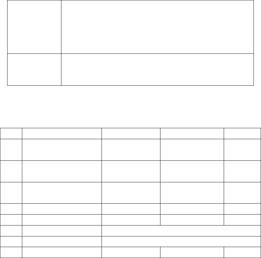
1.按人機介面右上角及左上角進入下圖 2.1,按夾板 進入圖 2.2.
圖 2.1
2.按支撐設定 進入圖 2.3.
圖 2.2
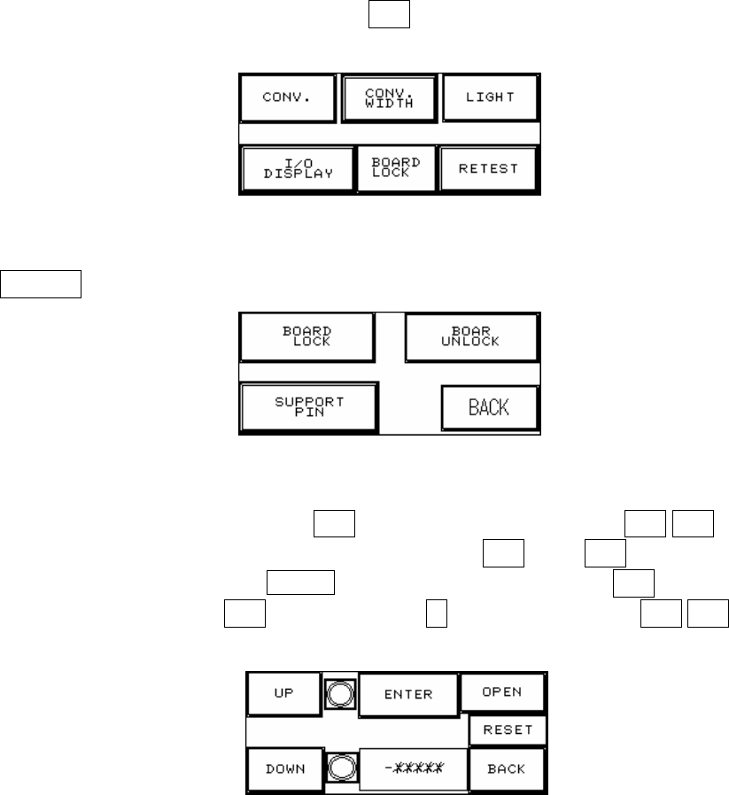
3. 將待測板放在進板 Sensor 處,然後按輸入,待測板會進入到定位,再按 上升/下降按鈕,寸動
調整上/下,首先需調至下限位置(下限指示燈亮),然後按下歸零,再按上升調至待測板所要支撐
的位置,如下圖 2.5 所示,同時在 -******處顯示設定值,設定完成後需按返回鈕即可,若無選購
此配備或不使用時,請勿必按開啟,並在圖 2.4 選擇否(否則會無法復歸),在上升/下降按鈕的右
側各為上升及下降的極限 SENSOR 指示燈,若該燈亮即表示已到達極限.
圖 2.3