N7201A617E00_0317.pdf - 第190页
NPM-W 2 EJM7DE-MB-06 M-00 Explains the method for greasing the nozzle holde r us ing the 12-nozzle head as an example; however, the same pro cedure is a lso applicable to the light weight 16- and 8-nozzle he ad. Tool use…

NPM-W2 EJM7DE-MB-06M-00
6-2-8
Every
560
hours
PeriodicPeriodicPeriodicPeriodic
inspection
NPM-W2 EJM7DE-MB-06M-00
Explains the method for greasing the nozzle holder using the 12-nozzle head as an example; however, the
same procedure is also applicable to the light weight 16-and 8-nozzle head.
Tool used: Syringe (BARRIERTA IEL/V)
Time required: 20 minutes for light weight 16-nozzle head, 15 minutes for 12-nozzle head, and 10 minutes for
8-nozzle head.
2
1
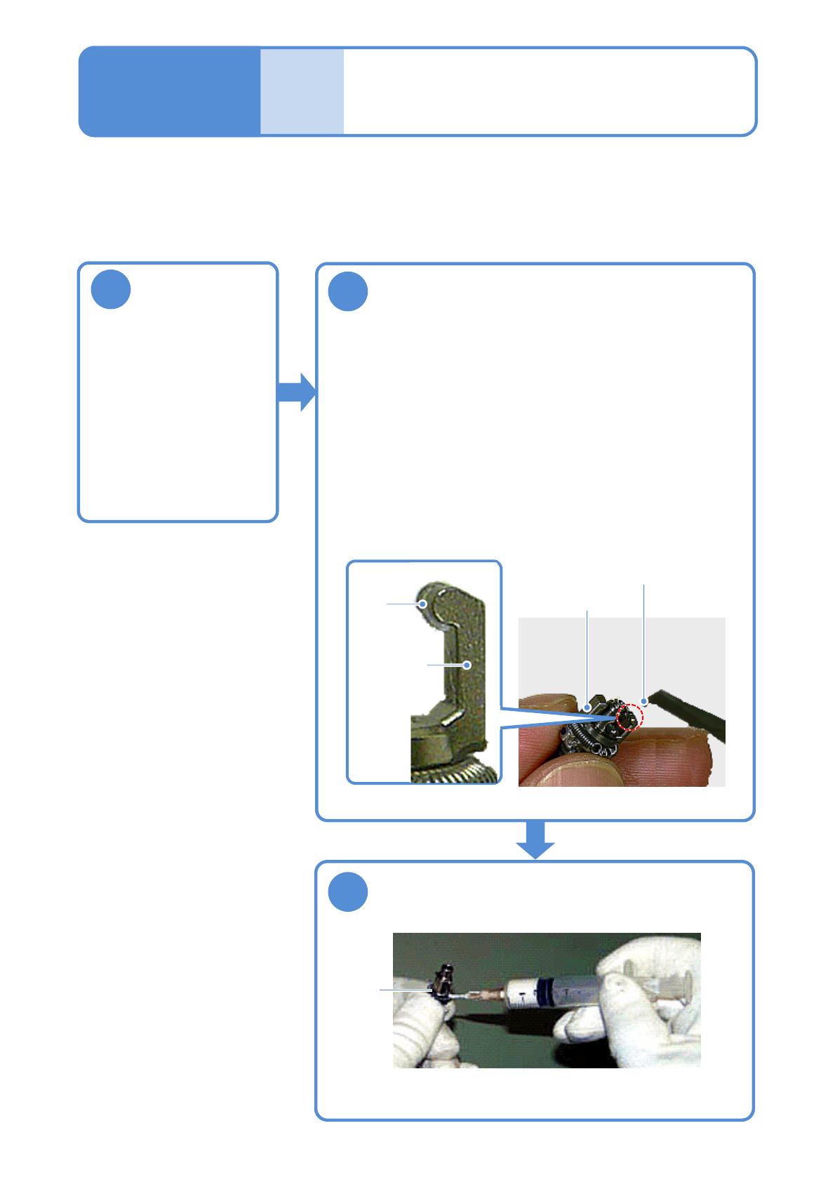
Greasing the nozzle
holder
Detach the
nozzle holder
(→P.5-2)
Refill grease to the oil groove at the clamp
claw
●With the clamp claw attached, apply grease using a small flat-
head screwdriver.
(To prevent grease from adhering to the portions around the
clamp claws)
●Grease: BARRIERTA IEL/V
●Wipe off any grease adhering to portions other than the oil
groove using a cotton swab.
●Be careful no grease adheres to the filter on the nozzle holder tip.
●Ensure that clamp claws are inserted to oil grooves before
installing the nozzle holder to the transfer head.
3
Apply grease to the contact surface of the
clamp claw and the spring for the clamp claw
pusher
●Apply grease lightly using a syringe.
●Grease: BARRIERTA IEL/V
6-3
Contact
surface
Clamp claw
Grease
Oil
groove
Clamp claw
Maintenance
6-3
NPM-W2 EJM7DE-MB-06M-00
Cleaning the nozzle (option) and
the nozzle changer
(option) 1
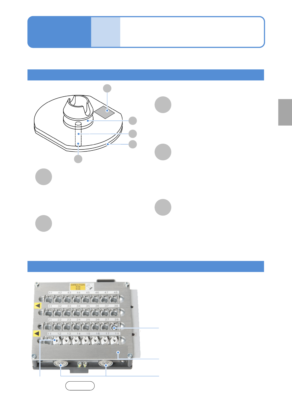
Name and role of nozzle parts
A
B
D
E
C
E
Nozzle taper surface
This is the part to be chucked by the
nozzle holder of placement head.
( Foreign bodies and contamination of the
taper surface and chucking groove can
cause an air leak and faulty chucking)
Nozzle reflector
This is a black-resin part. Parts are
recognized by reflecting the LED light from
the multi-recognition camera.
(Leaving this part dirty results in a
recognition error)
Nozzle tip (nozzle section)
This is the part that comes into direct
contact with a component and picks it up.
(Foreign bodies on the side results in a
recognition error. Leaving the pickup hole
dirty results in a pickup error)
Nozzle inside
(Foreign objects adhering inside the
nozzle hinder the pickup and placement
of components, and various detection
functions using vacuum pressure)
Nozzle flange upper surface
The nozzle type and serial No. are shown
by the 2D code. The 2D code area is
recognized by the head camera.
(Leaving this part dirty results in a
recognition error)
Nozzle changer
This is the unit that stocks nozzles. The transfer
head automatically changes nozzles before placing
components are changed.
Nozzle changer upper surface
(Any contamination of the nozzle changer
upper surface allows contaminants to adhere
to the nozzle reflector, resulting in
recognition errors)
6-4-1
Explains the method for cleaning a nozzle and a nozzle changer.
A
D
B
C
●Slide the shutter to the left when you manually
insert or remove nozzles.
Shutter
Maintenance
6-4
Nozzle
Front side
Shutter bearings
(Two each on both front and rear)
Every
560
hours
PeriodicPeriodicPeriodicPeriodic
inspection