N7201A617E00_0317.pdf - 第284页
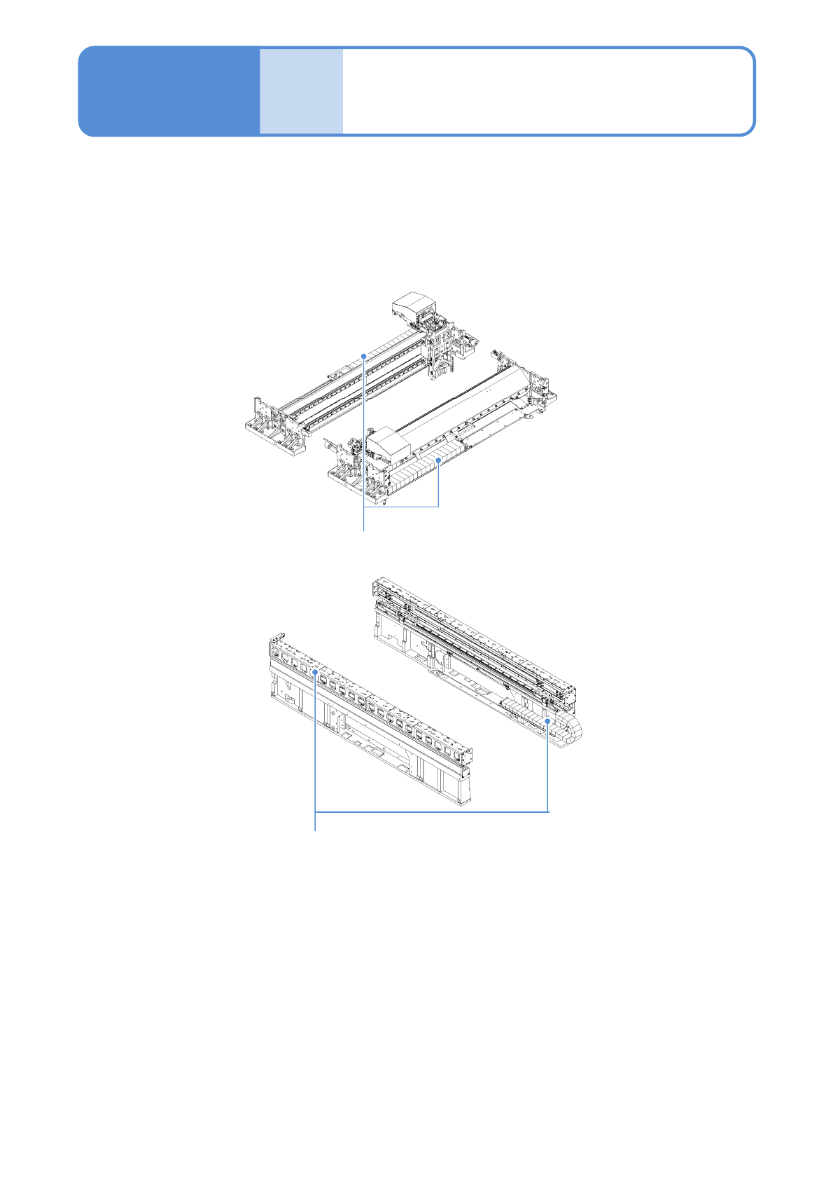
NPM-W 2 EJM7DE-MB-10M-00 10-2 Maintenance 10-2 Tool used: None Time required: 5 minutes X-axis cable bearer Y-axis cable bearer ● If the cable bearer is exhausted, the operating sound w ill become loud and it will cause …
NPM-W2 EJM7DE-MB-10M-00
10-1-2
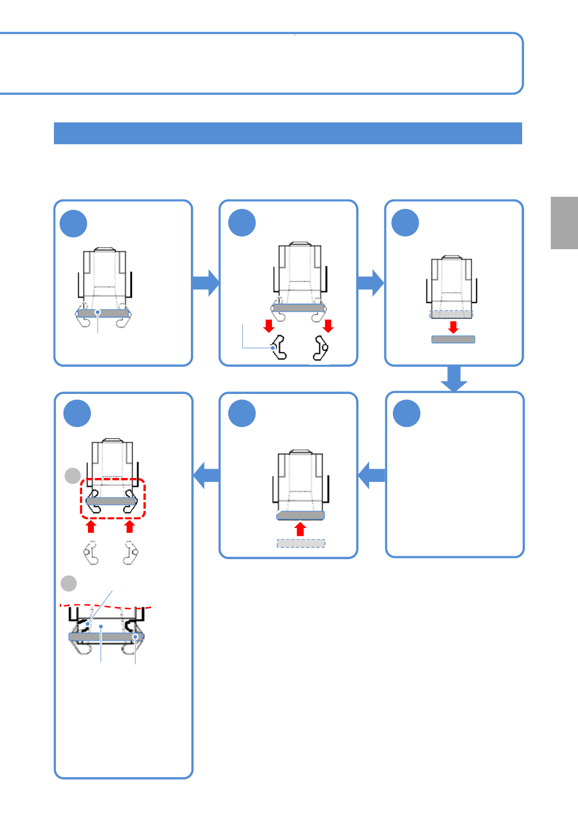
3-nozzle head
Tool used: None Time required: 10 minutes per head
1
6 5
●Check that the claws are
securely engaged in the
grooves in the nozzle
holder.
Push in the
clamp claw
Lightly pull the
spring for holding
clamp claws
2 3
Pull the clamp
claws
Remove the
spring for holding
clamp claws
Attach the spring
for holding clamp
claws
4
■When there is no
damage or wear
Check the part,
and if any
damage or wear
out is found,
replace it
●Clean it and apply
grease. (→P.5-2)
A
Spring for
holding
clamp claws
Nozzle
holder
A
Detail
Groove of the
nozzle holder
Spring for holding
clamp claws
Clamp
claws
● When you perform maintenance while the head is attached to the machine, observe the followings.
・Be careful not to fall parts.
・Prepare the plate in the case of falling the components.
Every
18000
hours
Periodic
inspection
NPM-W2 EJM7DE-MB-10M-00
10-2
Maintenance
10-2
Tool used: None Time required: 5 minutes
X-axis cable bearer
Y-axis cable bearer
●If the cable bearer is exhausted, the operating sound will become loud and it will cause breakage to wire
and tube. Inspect them after using about 18000 hours. If any part wears out, replace it.
● To replace the parts, contact us.
Inspecting the cable
bearer (XY unit)
NPM-W2 EJM7DE-MB-10M-00
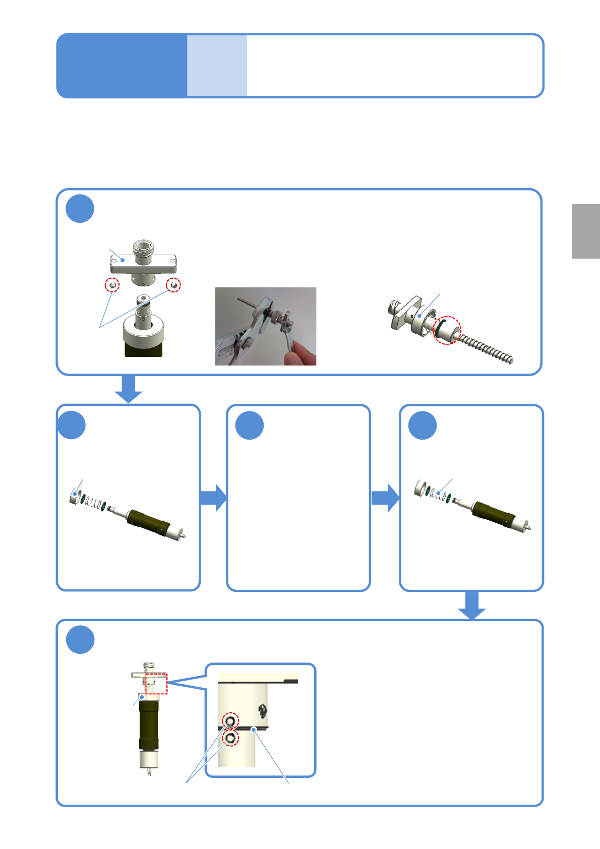
Replacing the spring 1
(dispensing head(option))
10-3-1
Tool used: Allen wrench Time required:10 minutes
●Be sure to replace it at the consumable parts replacement cycle.
●Detach the screw unit from the machine before work.(→P.4-2-5)
Maintenance
10-3
1
Loosen setscrews of the screw unit and detach the propeller
Setscrews
Propeller
●If it is difficult to remove the
propeller, hold the center of the
screw shaft with the pliers and
disassemble it.
●There is no problem if the center
of the screw shaft is scathed.
Upper cap
Spring
2
Loosen the upper
cap to detach it
(turn in a clockwise
direction)
3
Draw out the
screw shaft
about 10mm of
the screw unit
Upper cap
4
Replace the
spring
●These two collars are the
same. There is no
difference between front
and rear sides.
5
Put the screw unit back together again
●Tighten the upper cap (turn in a
counterclockwise direction), fix the screw
shaft, and attach the propeller.
●When the markings are aligned, tighten
the screws.
Be careful not to leave any clearance .
Marking
Upper cap
Every
18000
hours
Periodic
inspection