N7201A617E00_0317.pdf - 第299页
NPM-W 2 EJM7DE-MB-11M-00 11 - 2 This is a function used when a head is attached to si ngle axis on the machine or no head is attached on both sides an d a PCB b eing trans ported passes through. For how to insta ll the a…
NPM-W2 EJM7DE-MB-11M-00
11-1-7
Head and nozzle
changer replacement 4
1
2
3
Maintenance
11-1
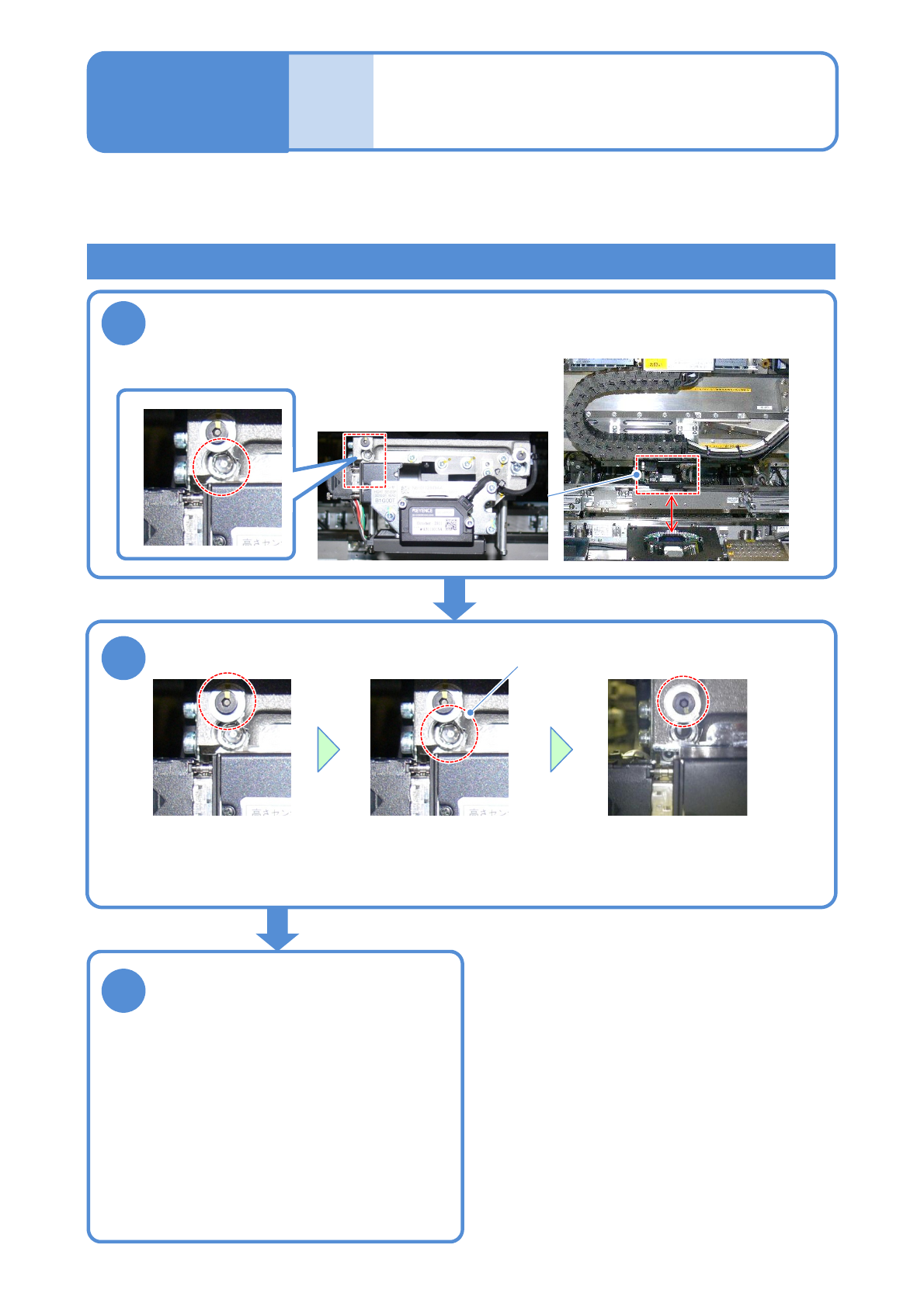
Attaching the old type head (Removing fixing bolts)
When the old type head is attached to NPM-W2, remove the unused fixing bolts before performing step 3 in
“Attaching a head” (→P.11-1-3) and fix the removed bolts to the storage place in the machine. The
operations are described here.
Tool used: Allen wrench (5 mm and 2.5 mm) Time required: 3 minutes
Move the head to the position where you can see the bolt
(Align the center of the head to the one of the multi-recognition camera)
Remove a fixing bolt
Lower left of a head
●Remove the upper bolt. ●Remove the lower fixing
bolt.
●Put the upper bolt to the
original position.
Fixing bolt
●You need to carry out the operation that the
fixing bolts are removed from the storage
position and put them back to the original
position. After the old type head is removed,
put the fixing bolts back to the original position
in the reverse order by referring to the
operation to remove the fixing bolts described
in this page.
■When the old type head is removed and
the current head is attached
Store the removed fixing bolt
NPM-W2 EJM7DE-MB-11M-00
11-2
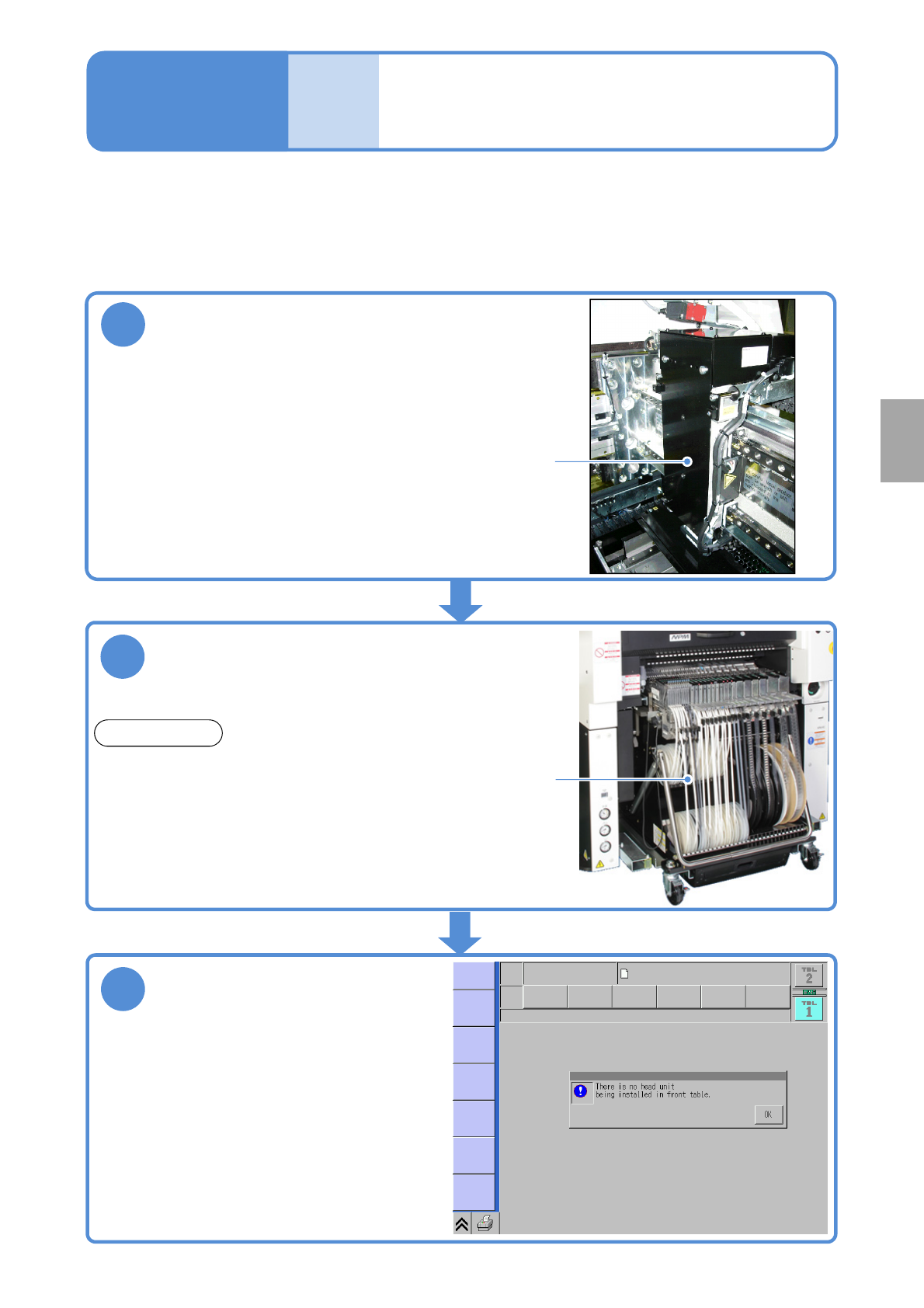
This is a function used when a head is attached to single axis on the machine or no head is attached on both
sides and a PCB being transported passes through. For how to install the attachment without head, see Head
and nozzle changer replacement (→P.11-1)
Maintenance
11-2
2
Install a feeder cart
Attachment without
head
●Machine will not operate unless installed.
1
Install the attachment without head to the
axis which does not install the head
Attachment
without head
■Machine conditions when this function is used
●Machine will not operate unless installed.
3
Power ON
●Make sure that the screen on the right appears
after turning ON the power.
(The screen indicates for the front head.)
Feeder
cart
REFERENCE
The safety cover (option) can be used instead of a
feeder cart.
Replacement
NPM-W2 EJM7DE-MB-11M-00
11-3-1-1
1
1
3
+
(The PCB-support block goes up so
that you can remove now)
(The message of removing the support
pin unit is displayed)
4
8
Detach the feeder cart
Confirm the message
2
3
+
(→P.3-2)
Cover the multi-recognition
camera with a cloth
10
2
Confirm the message
6
5
Servo switch OFF
Open the safety cover
7
9
Mode
switch
Maintenance
11-3-1
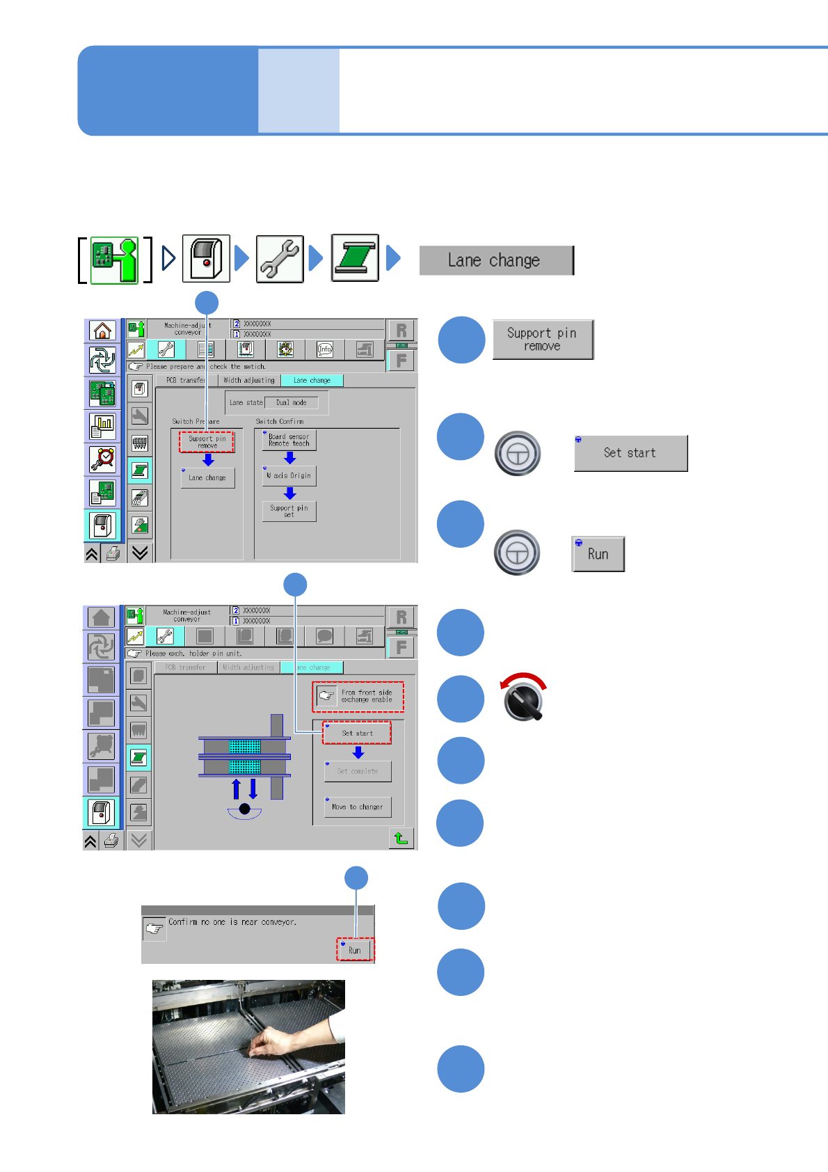
Switching to the single
lane mode
Remove the PCB-support plate
●It will keep foreign bodies from entering
the camera lens during the work.
●Be careful not to drop foreign bodies on
the multi-recognition camera (LED
lighting) or bump it.
When the machine specification is dual conveyor, switching the mode allows you to use the machine either for
single conveyor or dual conveyor.
●Follow the procedure below for switching. In this case, we explain to switch from dual conveyor to single
conveyor. Take the same procedure for switching from single lane mode to dual lane mode.
Replace the PCB-support block
(→P.5-3-2)
Fold the feeder table cover to the
back