N7201A617E00_0317.pdf - 第354页
NPM-W 2 EJM7DE-MB-13M-00 + 1 Plane cor r ection XY 1 Explains the method for calibrating the plane correct io n XY, taking for an example, the 12-nozzle head; however, the same method can also be applied to the light wei…
NPM-W2 EJM7DE-MB-13M-00
13-2-2
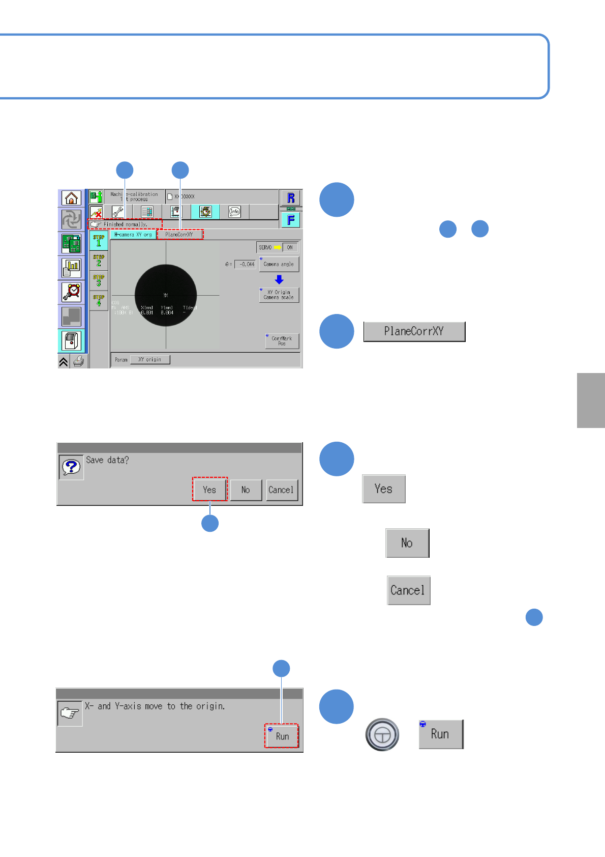
Confirm the message
6
6
●When you do not save the data
●To cancel
(The screen remains as it is in . )
5
Confirm the message
7
(XY unit moves to the origin)
+
7
Confirm that it has been
successfully completed
4 5
4
5
●Perform steps to for the
other table.
1
4
Calibration
NPM-W2 EJM7DE-MB-13M-00
+
1
Plane correction XY 1
Explains the method for calibrating the plane correction XY, taking for an example, the 12-nozzle head;
however, the same method can also be applied to the light weight 16-, 8-, and 3-nozzle heads. For the
inspection head (→P.13-17-1)
●For dual conveyor specifications, perform calibration in single lane mode. (→P.11-3)
●Place the plane correction jig on the transfer conveyor to the left or right of the machine by hand and
operate it. (One plane correction jig: N210147296AB)
●Do not turn OFF the power of the machine during calibration.
●Remove all the PCB support pins before performing plane correction.
●Calibrate it at the front to enhance workability.
Check that there are no PCBs
present inside the machine
●If ‘error’ message appears, remove all
the PCBs remaining inside the machine,
and try again.
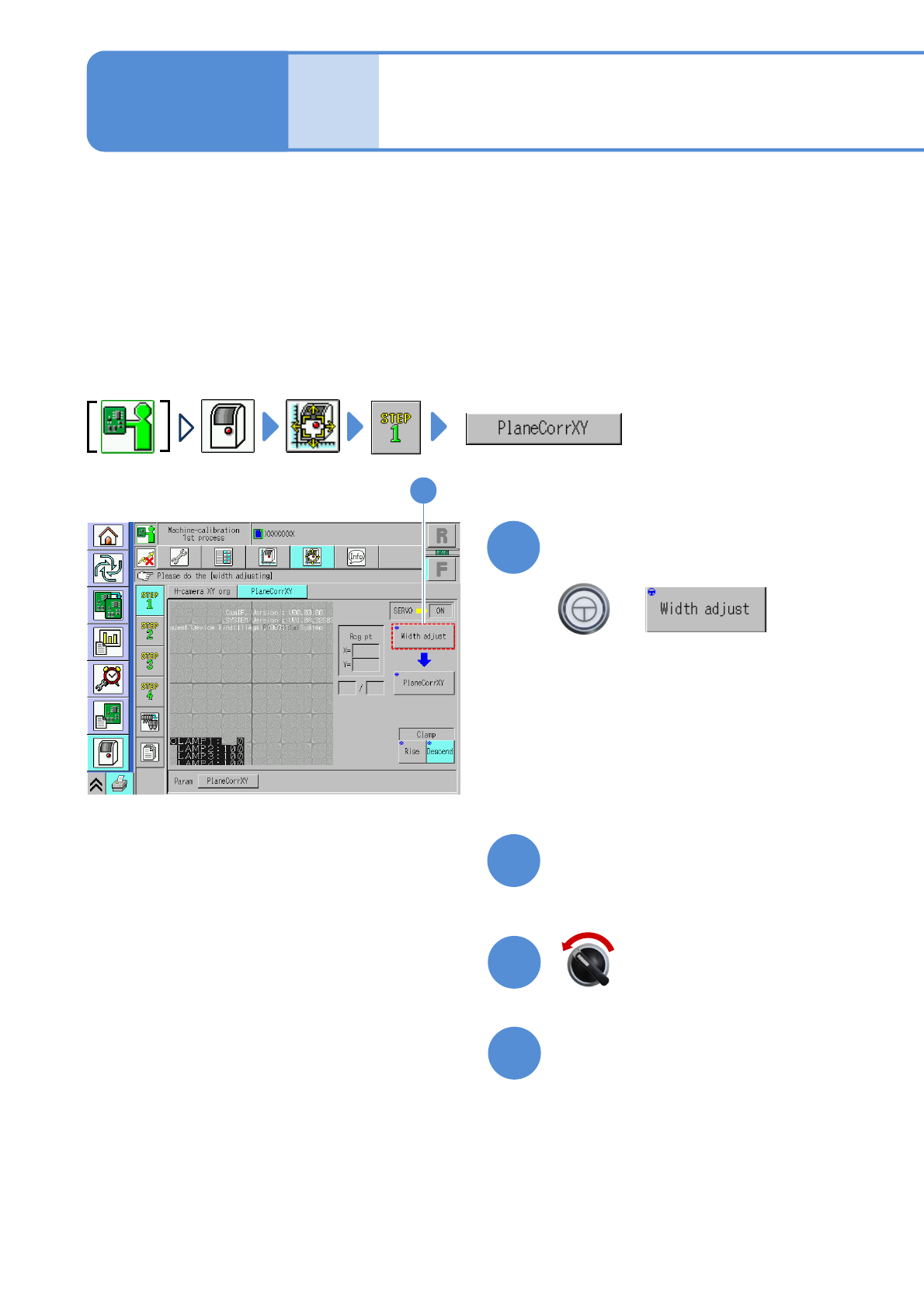
1
13-3-1
(The width is adjusted)
(The head moves to the retraction
position.)
Maintenance
13-3
2
Prepare for the first plane
correction XY
4
3
Open the safety cover
Servo switch OFF
NPM-W2 EJM7DE-MB-13M-00
5
13-3-2
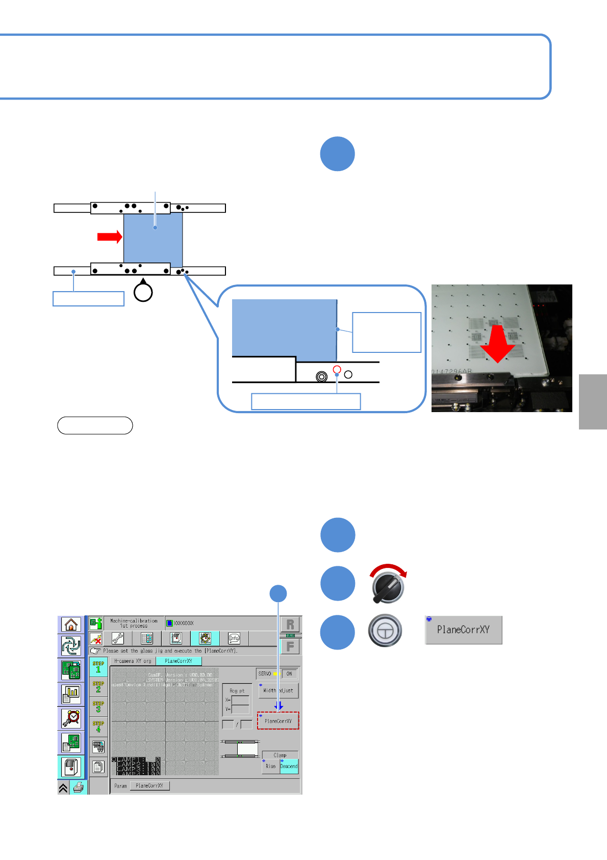
Set the plane correction jig
NOTICE
• The above figure is based on the front reference. As for the rear reference, place it on the conveyor so
that [FIXED RAIL SIDE (TYPE A)] on the plane correction jig is situated in the back in relation to the
operator.
• The reference hole for the plane correction differs from the one for accuracy verification. Be sure to
use the correct one.
Calibration
6
Close the safety cover
7
Servo switch ON
+
8
8
Plane correction jig
Operator
②
Reference rail
Plane correction
jig
Right edge of
plane
correction jig
Reference hole A
③
①Set the place correction jig’s edge that
[FIXED RAIL SIDE (TYPE A)] is
printed, to the reference rail side.
②Move the plane correction jig with hand
and align the right edge of the plane
correction jig to the reference hole A.
③Attach the plane correction jig to the
reference rail.