N7201A617E00_0317.pdf - 第355页
NPM-W 2 EJM7DE-MB-13M-00 5 13-3 -2 Set the plane correction jig NOTICE • The above figure is based on the front reference . As fo r the rear reference, place it on the conveyor so that [FIXED RAIL SIDE (TYPE A)] on the p…
NPM-W2 EJM7DE-MB-13M-00
+
1
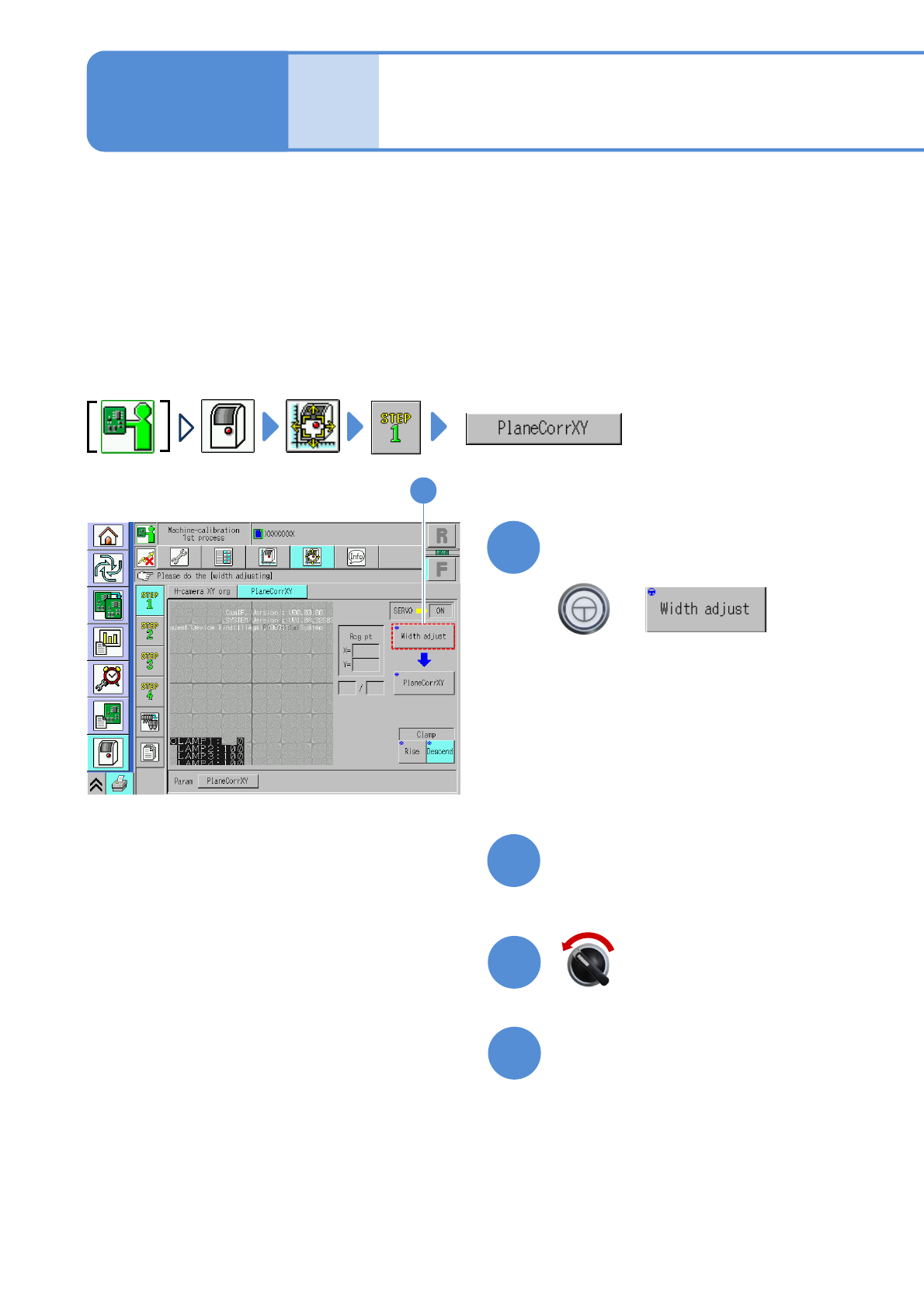
Plane correction XY 1
Explains the method for calibrating the plane correction XY, taking for an example, the 12-nozzle head;
however, the same method can also be applied to the light weight 16-, 8-, and 3-nozzle heads. For the
inspection head (→P.13-17-1)
●For dual conveyor specifications, perform calibration in single lane mode. (→P.11-3)
●Place the plane correction jig on the transfer conveyor to the left or right of the machine by hand and
operate it. (One plane correction jig: N210147296AB)
●Do not turn OFF the power of the machine during calibration.
●Remove all the PCB support pins before performing plane correction.
●Calibrate it at the front to enhance workability.
Check that there are no PCBs
present inside the machine
●If ‘error’ message appears, remove all
the PCBs remaining inside the machine,
and try again.
1
13-3-1
(The width is adjusted)
(The head moves to the retraction
position.)
Maintenance
13-3
2
Prepare for the first plane
correction XY
4
3
Open the safety cover
Servo switch OFF
NPM-W2 EJM7DE-MB-13M-00
5
13-3-2
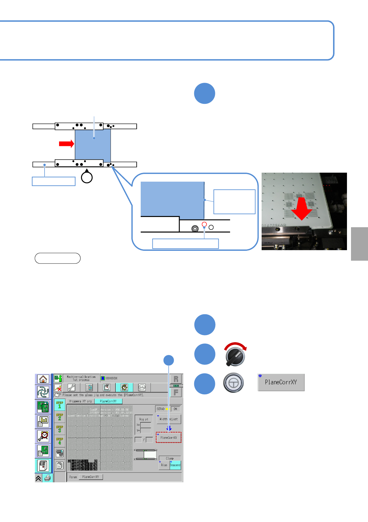
Set the plane correction jig
NOTICE
• The above figure is based on the front reference. As for the rear reference, place it on the conveyor so
that [FIXED RAIL SIDE (TYPE A)] on the plane correction jig is situated in the back in relation to the
operator.
• The reference hole for the plane correction differs from the one for accuracy verification. Be sure to
use the correct one.
Calibration
6
Close the safety cover
7
Servo switch ON
+
8
8
Plane correction jig
Operator
②
Reference rail
Plane correction
jig
Right edge of
plane
correction jig
Reference hole A
③
①Set the place correction jig’s edge that
[FIXED RAIL SIDE (TYPE A)] is
printed, to the reference rail side.
②Move the plane correction jig with hand
and align the right edge of the plane
correction jig to the reference hole A.
③Attach the plane correction jig to the
reference rail.
NPM-W2 EJM7DE-MB-13M-00
Plane correction XY 2
13-3-3
9
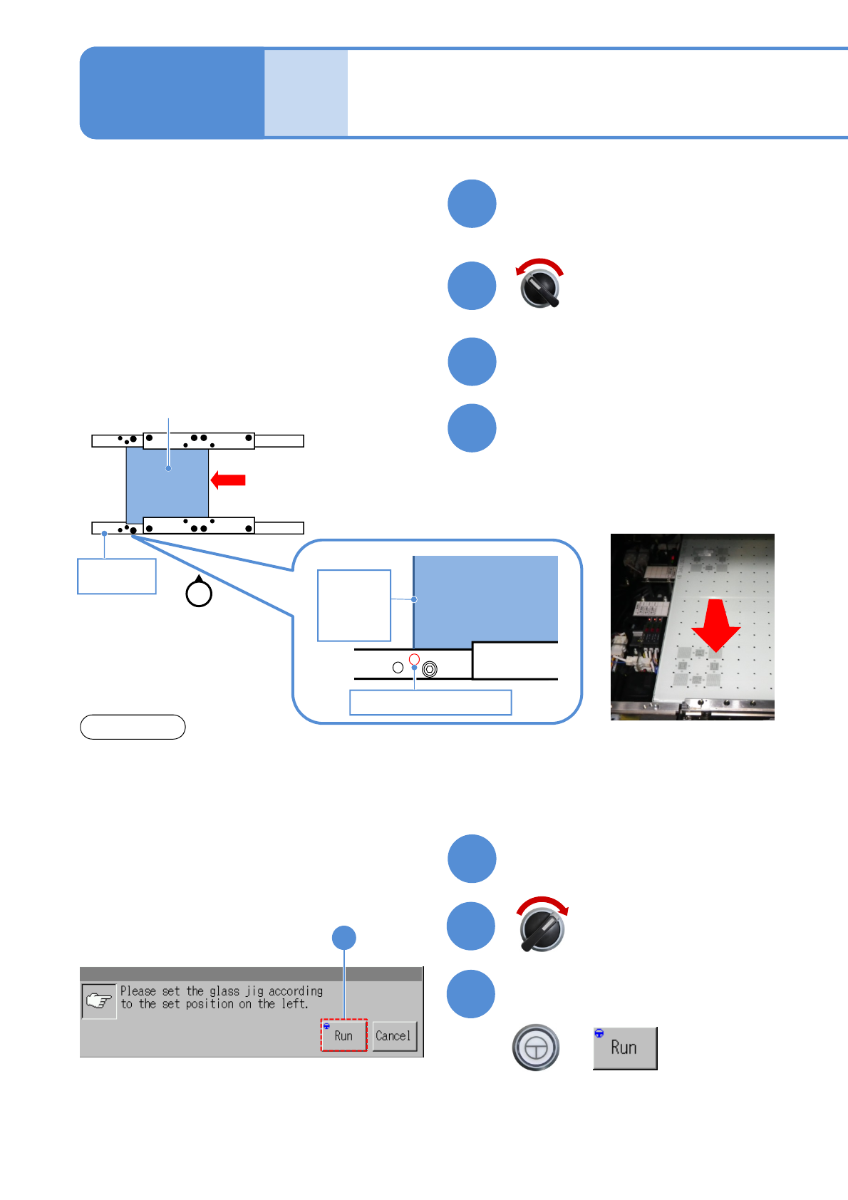
Prepare for the second plane
correction XY
11
10
Open the safety cover
12
NOTICE
Set the plane correction jig
Maintenance
13-3
13
Close the safety cover
14
15
Confirm the message
+
(Plane correction XY is measured on the
front and rear side, in that order)
(The head moves to the retraction
position)
Servo switch OFF
Servo switch ON
15
Plane correction jig
Reference
rail
①
Operator
Plane
correction jig
Reference hole B
Left edge
of plane
correction
Jig
②
①Move the plane correction jig with hand
and align the left edge of the plane
correction jig to the reference hole B.
②Attach the plane correction jig to the
reference rail.
・The above figure is based on the front reference. As for the rear reference, place it on the conveyor so
that [FIXED RAIL SIDE (TYPE A)] on the plane correction jig is situated in the back in relation to the
operator.
・The reference hole for the plane correction differs from the one for accuracy verification. Be sure to
use the correct one.