N7201A617E00_0317.pdf - 第357页
NPM-W 2 EJM7DE-MB-13M-00 13-3 -4 16 Confirm that it has been successfully completed 16 17 Confirm the message (The p lane corr ection XY data is s aved) 17 Calibration ● When you do not save the data ● To cancel (The scr…
NPM-W2 EJM7DE-MB-13M-00
Plane correction XY 2
13-3-3
9
Prepare for the second plane
correction XY
11
10
Open the safety cover
12
NOTICE
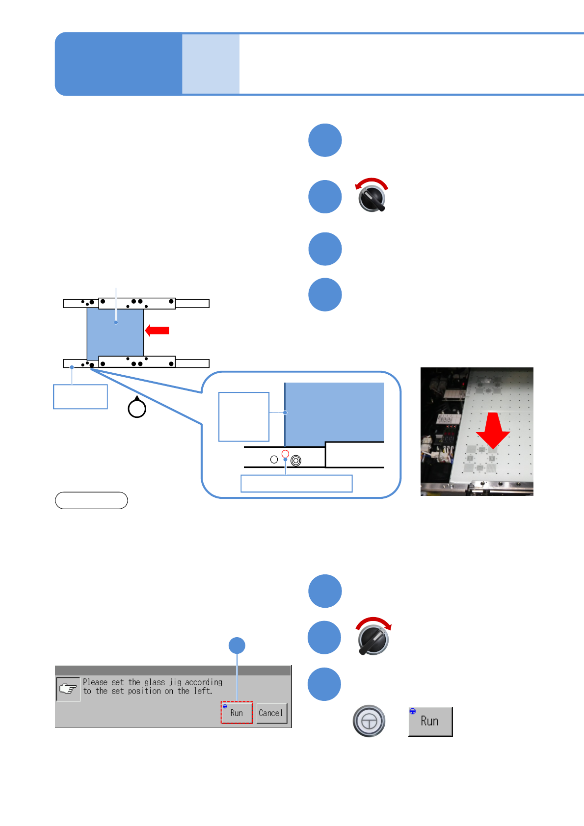
Set the plane correction jig
Maintenance
13-3
13
Close the safety cover
14
15
Confirm the message
+
(Plane correction XY is measured on the
front and rear side, in that order)
(The head moves to the retraction
position)
Servo switch OFF
Servo switch ON
15
Plane correction jig
Reference
rail
①
Operator
Plane
correction jig
Reference hole B
Left edge
of plane
correction
Jig
②
①Move the plane correction jig with hand
and align the left edge of the plane
correction jig to the reference hole B.
②Attach the plane correction jig to the
reference rail.
・The above figure is based on the front reference. As for the rear reference, place it on the conveyor so
that [FIXED RAIL SIDE (TYPE A)] on the plane correction jig is situated in the back in relation to the
operator.
・The reference hole for the plane correction differs from the one for accuracy verification. Be sure to
use the correct one.
NPM-W2 EJM7DE-MB-13M-00
13-3-4
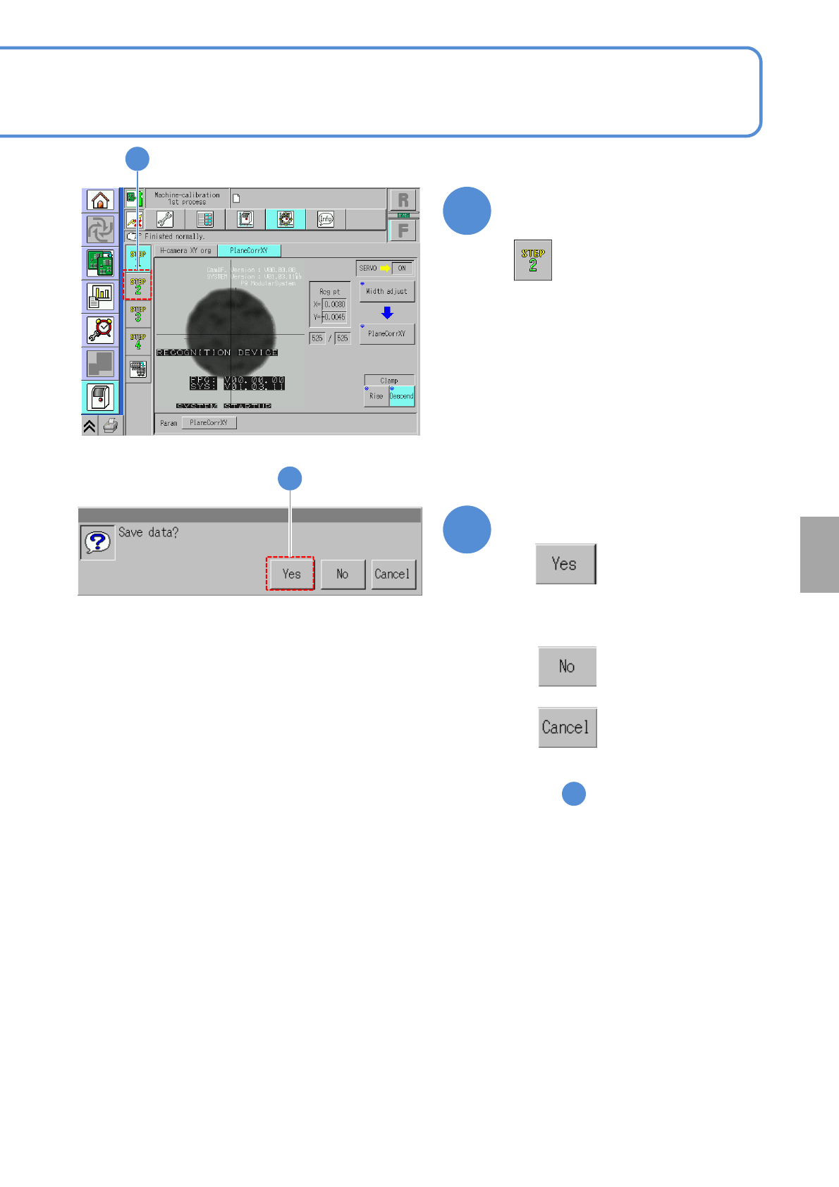
16
Confirm that it has been
successfully completed
16
17
Confirm the message
(The plane correction XY data is saved)
17
Calibration
●When you do not save the data
●To cancel
(The screen remains as it is
in )
16
NPM-W2 EJM7DE-MB-13M-00
Plane correction XY 3
18
13-3-5
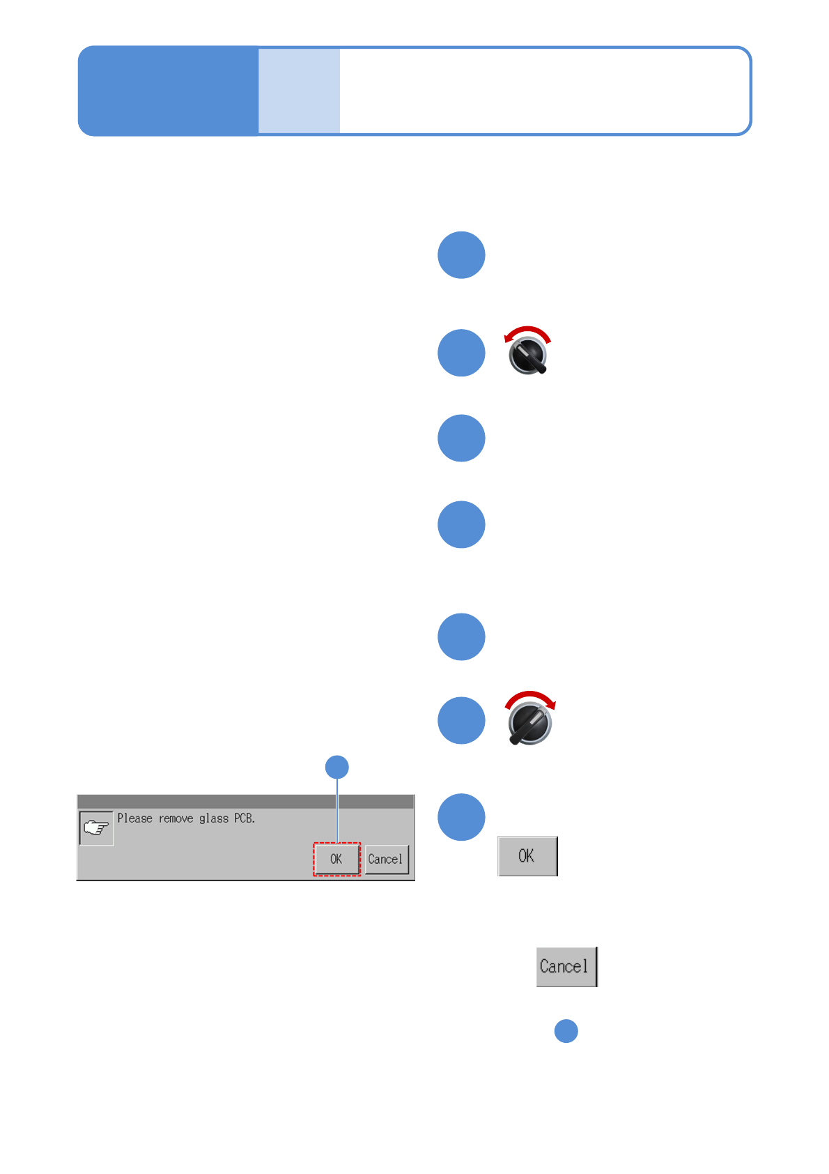
Prepare for removing the plane
correction jig
Maintenance
13-3
Open the safety cover
19
20
Push the plane correction jig
out of the machine by hand
through the left-hand or right-
hand transfer conveyor.
21
22
Close the safety cover
23
24
24
(Completes plane correction XY
operation)
Confirm the message
●To cancel
(The screen remains as it is
in )
16
Servo switch OFF
Servo switch ON