N7201A617E00_0317.pdf - 第394页
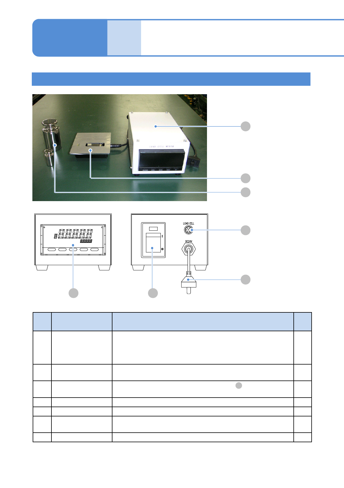
NPM-W 2 EJM7DE-MB-13M-00 Place- ment load Ho w to use placement load measur ement jig (option) 1 Jig configuration 13-8-2 -1 Maintenance 13-8-2 A B C F G D E No. Unit name Function Q’ty A Load cell meter The unit d esign…
NPM-W2 EJM7DE-MB-13M-00
13-8-1-10
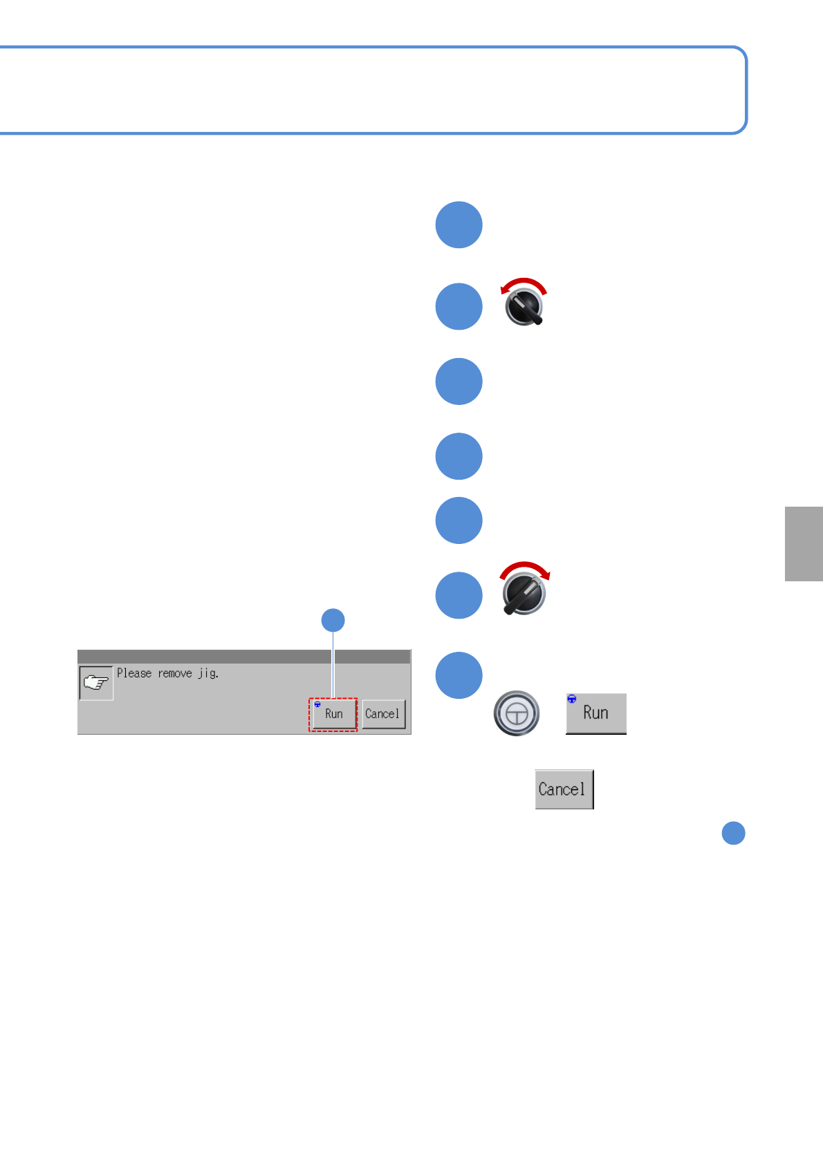
Calibration
Remove the placement load
measurement jig
Close the safety cover
Servo switch ON
Servo switch OFF
Open the safety cover
+
Confirm the message
■To cancel
(The screen remains as it is in )
Prepare to remove jig
44
47
48
49
45
46
50
34
50
NPM-W2 EJM7DE-MB-13M-00
Place-
ment
load
How to use placement load
measurement jig
(option) 1
Jig configuration
13-8-2-1
Maintenance
13-8-2
A
B
C
F
G
D E
No. Unit name Function Q’ty
A Load cell meter
The unit designed specifically for the 2-, 3-nozzle head that is used,
for example, in the load control calibration to replace the head.
Power supply specs.: 24 V DC 7 VA
Mass: 1.2 kg Dimension: 120 mm(W) x 8 0 mm(H) x 19 0 mm(D)
1
B Load cell
Load measurement sensor. Connect it to the load cell meter to use.
Mass: 600 g
1
C Weight
Weight to calibrate the load cell meter stated in .
Mass: 100 g/1 kg
1
each
D Display Displays a load value.
---
E Power switch Power switch of the load cell meter’s main unit.
---
F
Sensor cable
connector
Connect it to the load cell with the attached cable. ---
G Power cable Connect it to the feeder supply unit and supply the power.
---
A
NPM-W2 EJM7DE-MB-13M-00
13-8-2-2
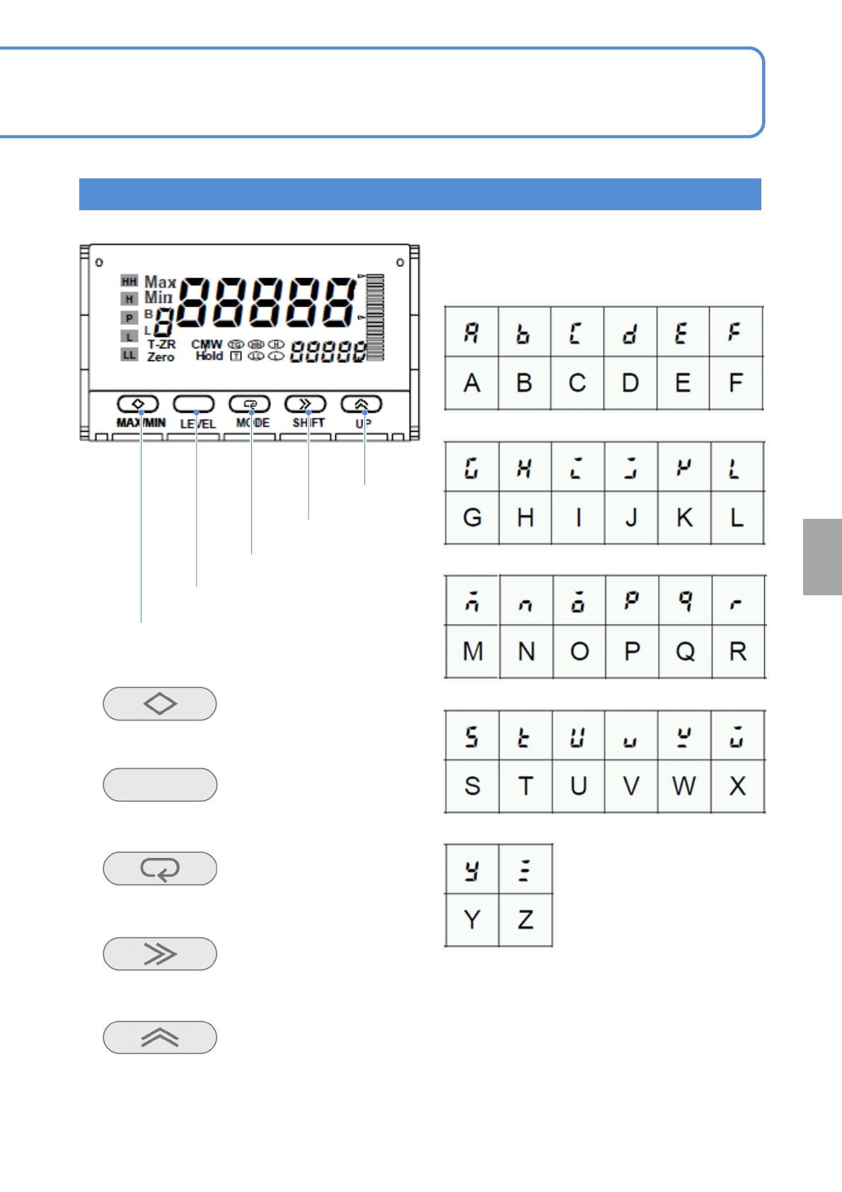
MAX/MIN
Resets or changes
the display between
Current, MAX and
MIN values
LEVEL
Changes the
value
MODE
Changes display
parameters
SHIFT
Changes values set
to parameters and
shift the digit of the
set values
UP
Changes the set
values and
sets/cancels zero
forcing
Each letter of the alphabet used in describing the
set data or contents is as follows.
Names and functions of operation buttons
MAX/MIN
LEVEL
MODE
SHIFT
UP
Calibration