N7201A617E00_0317.pdf - 第399页
NPM-W 2 EJM7DE-MB-13 M-00 13-8-2 -6 19 19 20 21 19 20 21 Confirm the decimal point position (The decimal point position is set) ■ To change (The screen display flashes) Hold down for at least a second (Returns to the ope…
NPM-W2 EJM7DE-MB-13M-00
Place-
ment
load
How to use placement load
measurement jig
(option) 3
13-8-2-5
Maintenance
13-8-2
(The value is displayed, and the lamp
flashes)
(Teaching is complete and then the lamp
changes from flashing to illumination)
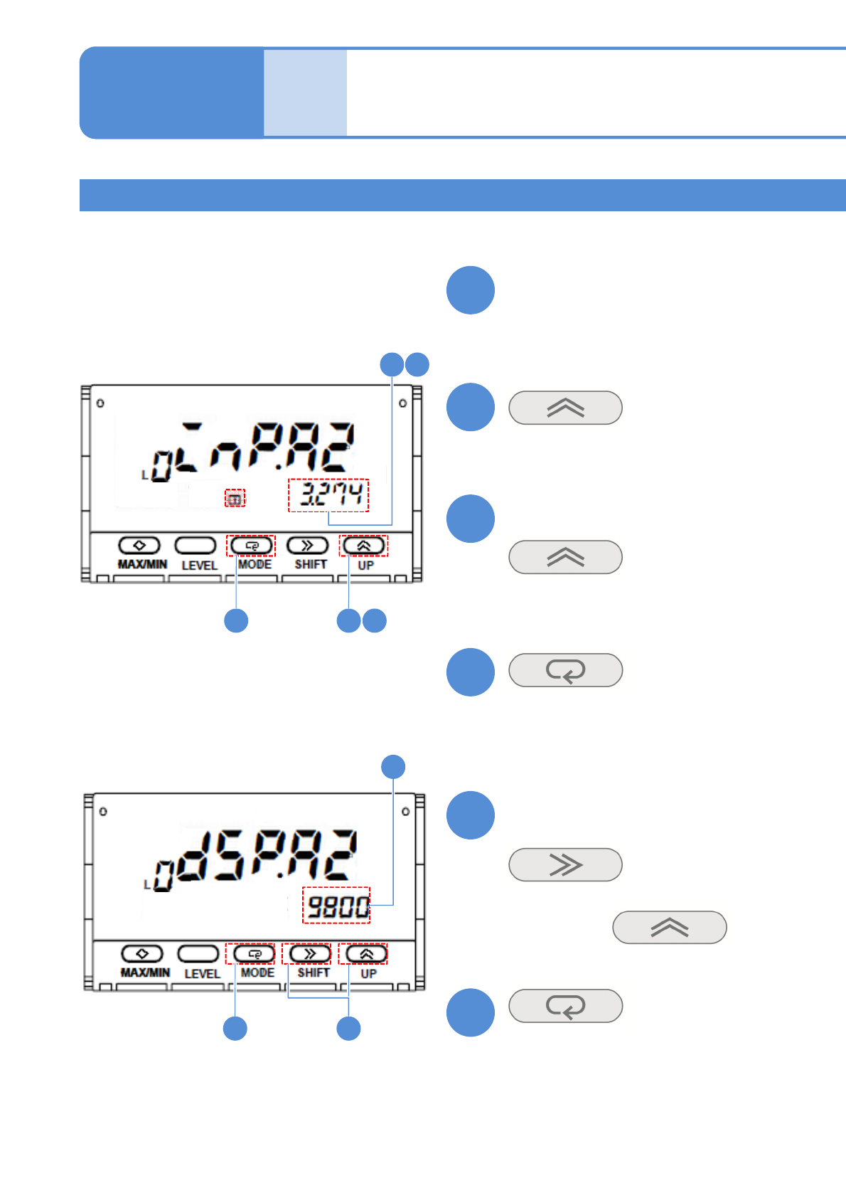
Confirm that the display value
becomes stable
(The input value 2 is set)
Confirm the display value
(The display value 2 is set)
■If the screen display differs
(The display flashes)
Choose it with
14
151416
15
17
1718
13
14
15
16
17
18
Calibration method 2
Put a 1kg weight on the load cell
NPM-W2 EJM7DE-MB-13M-00
13-8-2-6
19
19
20
21
192021
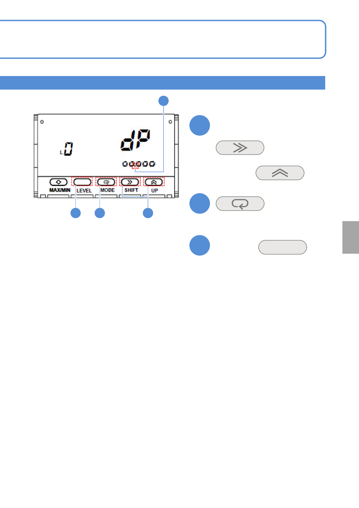
Confirm the decimal point position
(The decimal point position is set)
■To change
(The screen display flashes)
Hold down
for at least a second
(Returns to the operation level)
Choose it with
Calibration
NPM-W2 EJM7DE-MB-13M-00
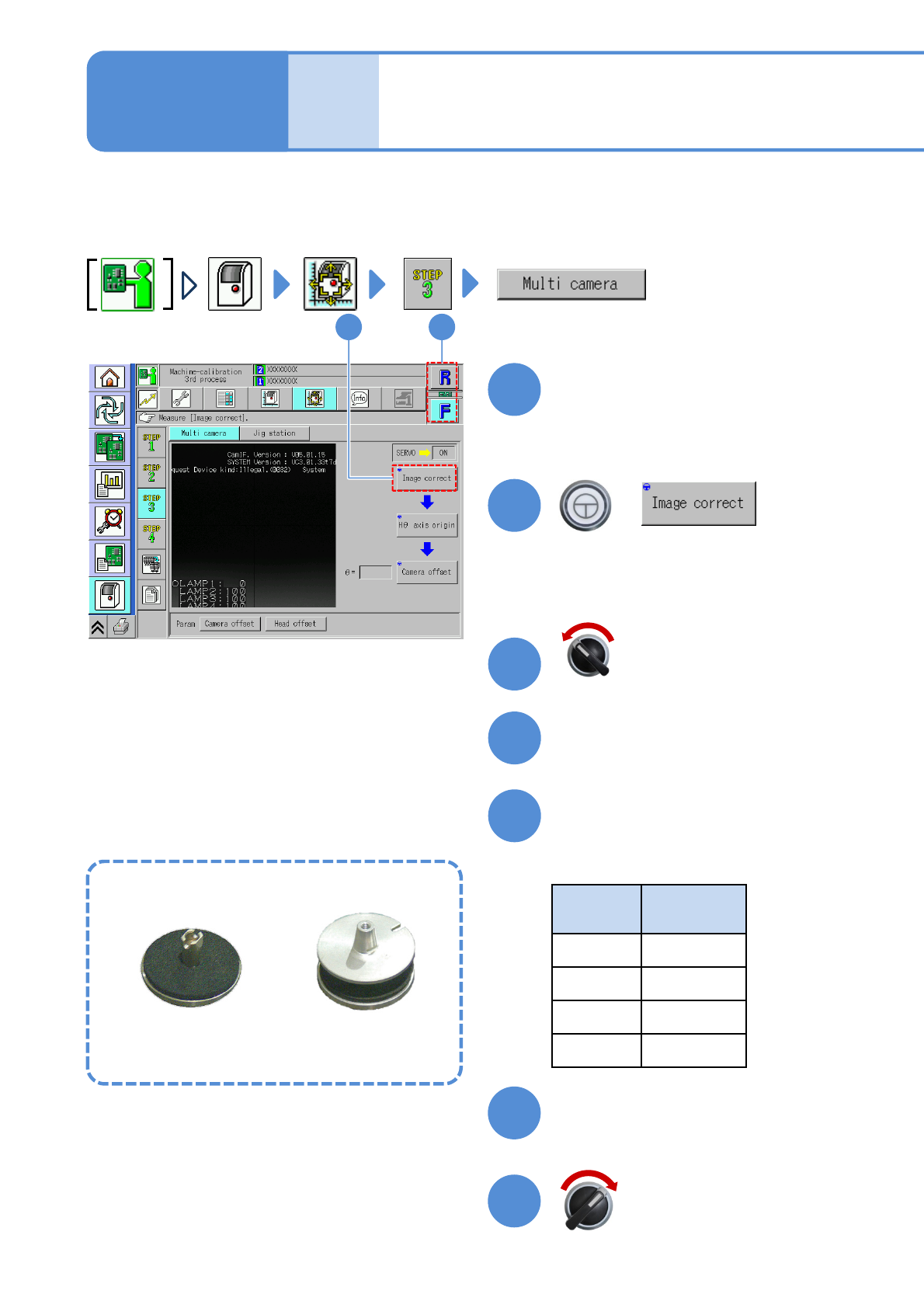
Multi-recognition
camera 1
Explains the multi-recognition camera operating procedure, taking for an example, the 12-nozzle head;
however, the same procedure can also be applied to the light weight16-, 8-, and 3-nozzle heads.
Remove the feeder, if any, from the table you are going to calibrate beforehand.
Choose a head
+
13-9-1
●Choose the head you want to calibrate.
Maintenance
13-9
12
2
1
(The head moves to the work position)
Open the safety cover
Install the multi-recognition
camera jig
●Nozzles used
Head
type
Nozzle
position
16 No. 5
12 No. 4
8No. 3
3No. 2
Servo switch OFF
3
4
5
Close the safety cover
Servo switch ON
6
7
Multi-recognition camera jig
For light weight16-, 12-,
8-nozzle head
For 3-nozzle head