N7201A617E00_0317.pdf - 第402页
NPM-W 2 EJM7DE-MB-13M-00 13-9 -3 Multi-r ecognition camer a 2 Maintenance 13-9 Servo switch ON Close the safety cover 15 14 + Confirm the message ■ To cancel (The screen remains as it is in ) Servo switch OFF Prepare to …
NPM-W2 EJM7DE-MB-13M-00
13-9-2
Calibration
+
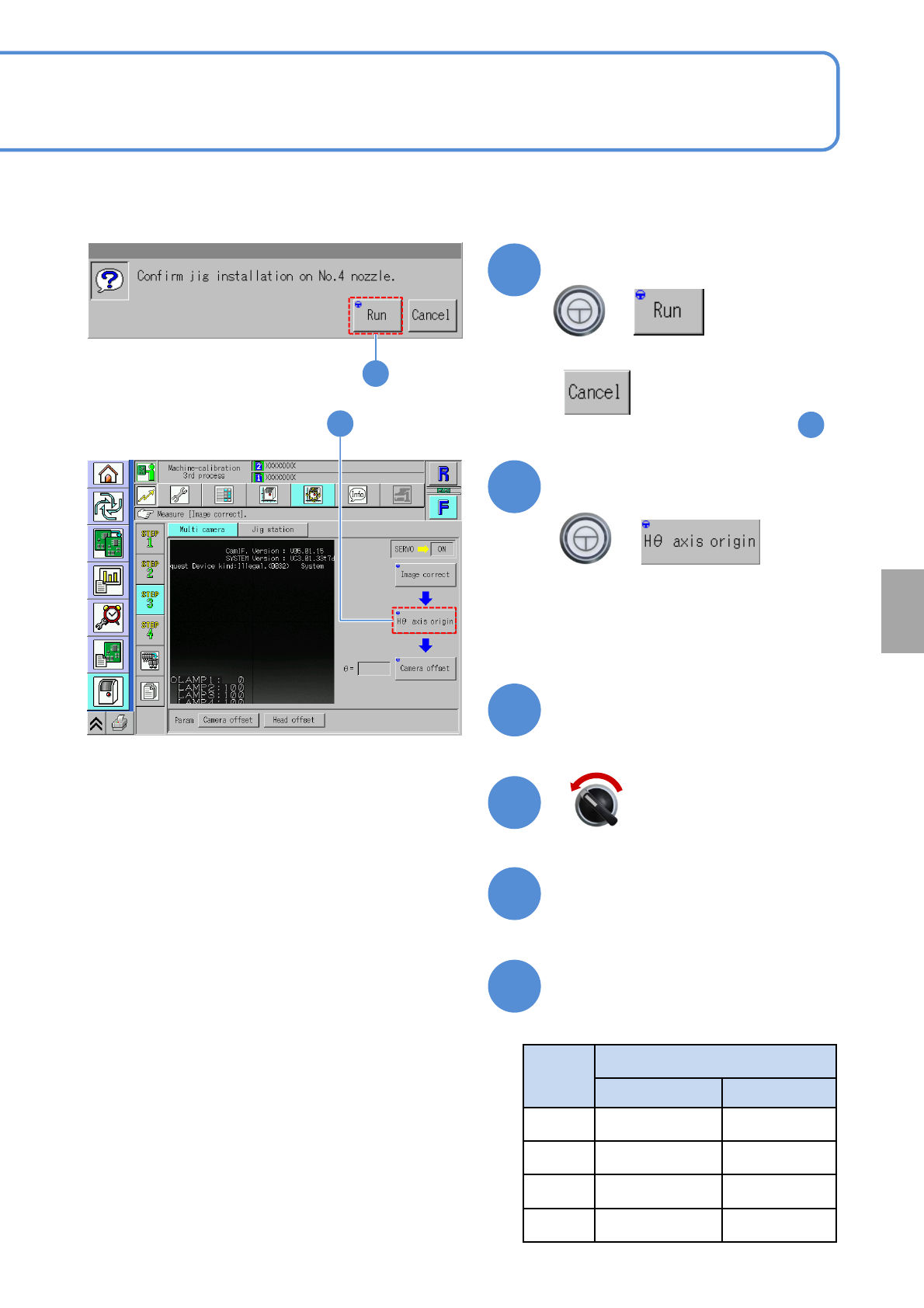
Confirm the message
■To cancel
(The screen remains as it is in )
8
1
+
9
(The head moves to the work position)
9
Confirm that it has been
successfully completed
8
Prepare to attach the jig
Servo switch OFF
Open the safety cover
Head
type
Nozzle position
Before replace After replace
16 No. 5 No. 12
12 No. 4 No. 9
8 No. 3 No. 6
3 No. 2 No. 1
10
11
12
13
Replace the multi-recognition
camera jig
●Nozzles that you confirm
NPM-W2 EJM7DE-MB-13M-00
13-9-3
Multi-recognition
camera 2
Maintenance
13-9
Servo switch ON
Close the safety cover
15
14
+
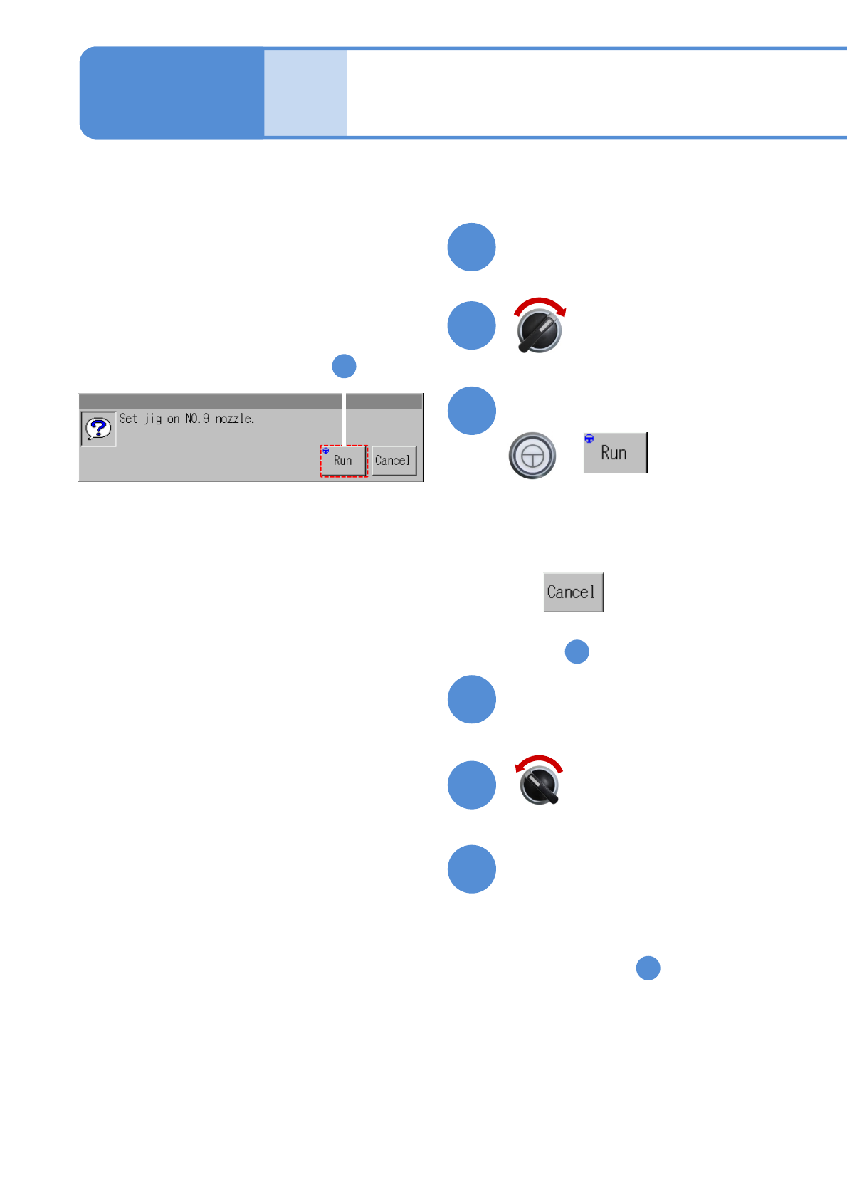
Confirm the message
■To cancel
(The screen remains as it is
in )
Servo switch OFF
Prepare to install the jig
Open the safety cover
(The multi-recognition camera is
calibrated)
1
Perform steps after .
■ For other than 3-nozzle head
■ For 3-nozzle head
Perform steps after this.
18
17
19
16
26
16
(The head moves to the work position)
NPM-W2 EJM7DE-MB-13M-00
13-9-4
Calibration
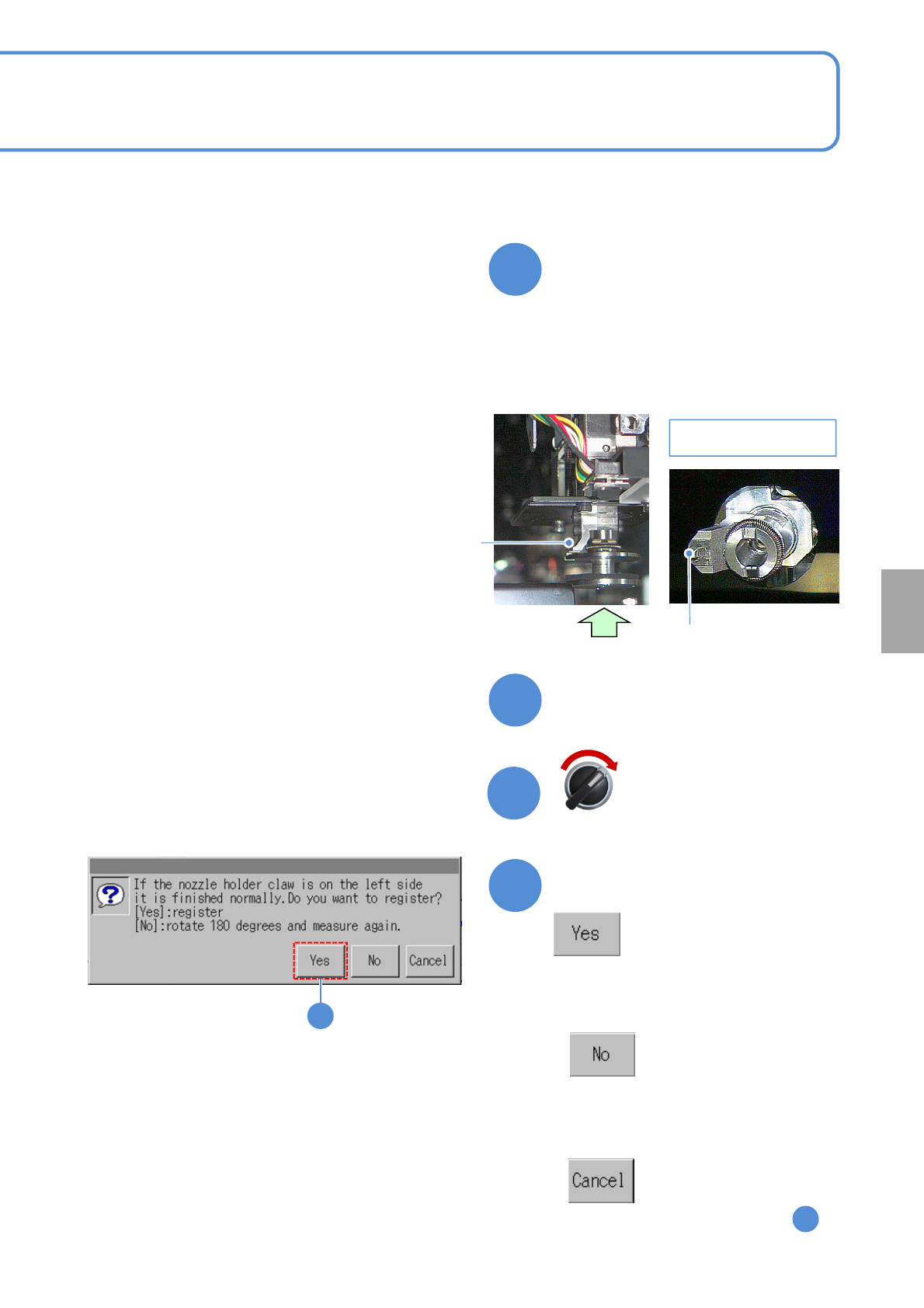
Confirm the head installation
angle
Close the safety cover
Nozzle holder claw
Arrow view A
A
Nozzle holder claw
●Check the direction of a nozzle holder
claw.
Front XY unit: The claw is rightside viewed
from the front side
Rear XY unit: The claw is left side viewed
from the rear side
Servo switch ON
Confirm the message
■To cancel
(The screen remains as it is in )
■If the nozzle holder claw is not on the
left side,
(Rotates 180 degree and measures
again)
20
21
22
23
1
23
(The head moves to the work position)