N7201A617E00_0317.pdf - 第408页
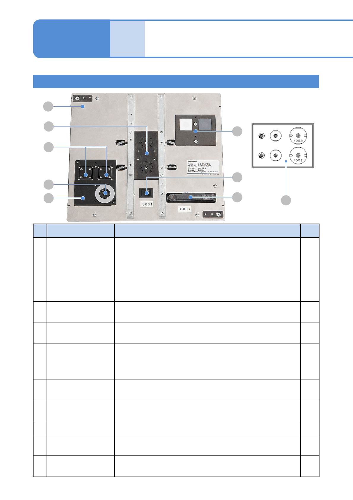
NPM-W 2 EJM7DE-MB-13 M-00 Jig sta tion 1 Jig station configuration 13-10 -1 Maintenance 13-10 D A E F G H B C I No. Unit name Functions Q’ty A Jig station This is the unit used for head parame ter calibratio n, for examp…
NPM-W2 EJM7DE-MB-13M-00
13-9-9
+
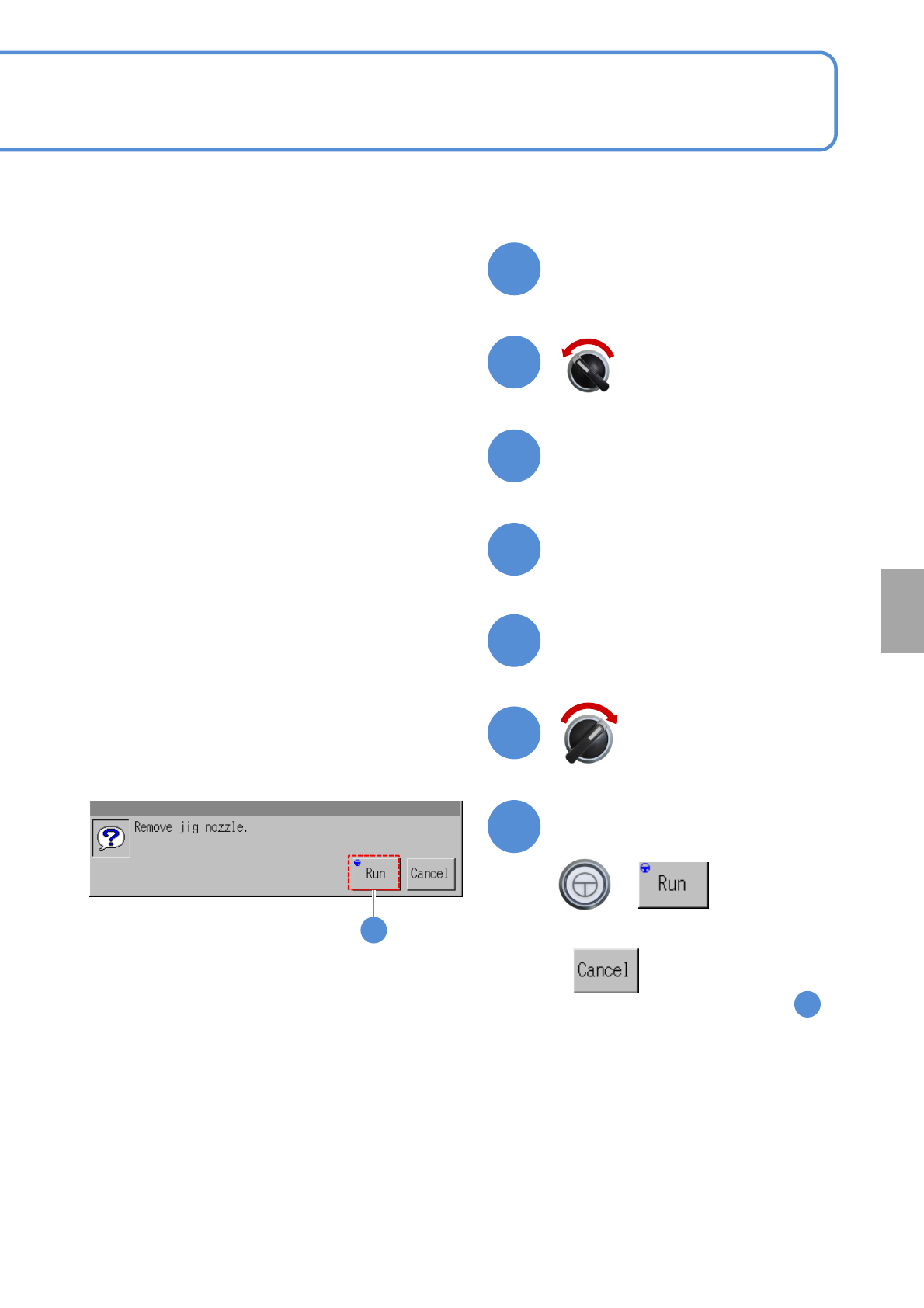
Confirm the message
■To cancel
(The screen remains as it is in )
Prepare to remove the jig
nozzle
Open the safety cover
Remove the jig nozzle
Close the safety cover
Servo switch ON
Servo switch OFF
41
42
43
44
45
47
46
38
47
Calibration
NPM-W2 EJM7DE-MB-13M-00
Jig station 1
Jig station configuration
13-10-1
Maintenance
13-10
D
A
E
F
G
H
B
C
I
No.
Unit name Functions Q’ty
A Jig station
This is the unit used for head parameter calibration, for example,
when you replace the head. It can be shared by all the heads.
Power specifications: 12V DC (8 AA batteries) Prepare on your own.
(→P.12-3 Replacing NPM batteries)
Caution: If the batteries are left inside, they may leak; therefore,
if you do not use the jig station for a long period,
remove and store them.
Mass: 1.5kg Dimensions: 240mm (W) x 215mm (D) x 35mm (H)
1
B Jig components
Jig components used for calibration.
They are used by installing to the jig station.
2
C
Multi-recognition
camera LED
Light luminosity jig
Jig used for luminosity calibration of LED lighting on the multi-
recognition camera. It is used by installing to the jig station.
1
D Calibration nozzle
Nozzle used for calibration.
For light weight 16-nozzle head, 12-nozzle head: 153AS nozzle
For 8-nozzle head : 184 nozzle
For 3-nozzle head : 1003 nozzle
2
each
E
Head camera LED
Light luminosity jig
The jig that is used in calibrating LED light’s luminosity on the head
camera is set to the place.
---
F Main power switch
When turning ON the power, green LED illuminates. (If not, replace
the battery)
---
G Photo sensor amplifier The sensor that detects jig components. ---
H Jig recognition section
It is used for recognition. Jig components are set to it when you
calibrate.
---
I Jig storage section
Jig components and light luminosity jig are set to this section before
calibration.
---
NPM-W2 EJM7DE-MB-13M-00
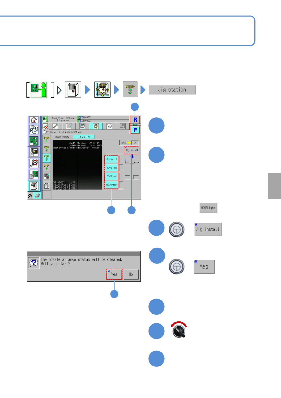
Explains the jig station operating method, taking for an example, the 12-nozzle head; however, the same
procedure can also be applied to the light weight16-, 8-, and 3-nozzle heads.
●Make sure that there are no nozzles present in the nozzle changer. Remove all the PCB support pins.
Choose a table
●Choose the table for calibration.
Choose a measurement item
(The selected items are displayed in
light blue color, and, all the rest, in
gray)
+
13-10-2
1
2 3
■For the placement head,
Choose all measurement items.
■For the dispensing head/2D inspection
head,
Choose only.
Calibration
Open the safety cover
Prepare to install the jig station
Servo switch OFF
3
2
1
7
6
5
4
4
(The width is adjusted)
(The head moves to the retraction position)
Confirm the message
+