N7201A617E00_0317.pdf - 第439页
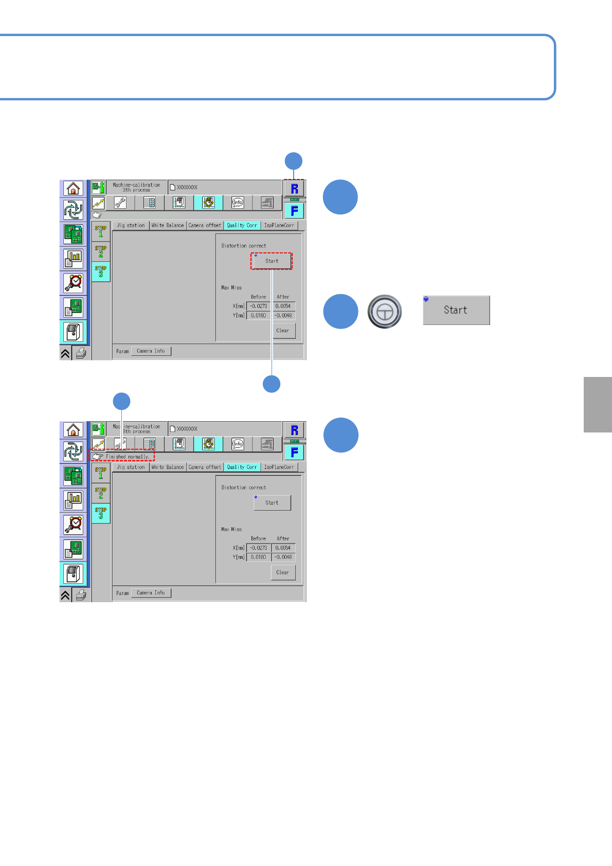
NPM-W 2 EJM7DE-MB-13 M-00 13-16 -2 6 7 8 Choose a table + 6 8 (The head operat es to measure the distortion) Confirm that it has been successfully completed Calibration 7 ● If an error occurs, check if the distortion cor…
NPM-W2 EJM7DE-MB-13M-00
Image quality correction
(2D inspection head)
13-16-1
Maintenance
13-16
The inspection head measures solder and component positions based on an image captured by the color
camera. This function corrects distortion of the camera image in order to make a precise measurement.
The distortion correction plate is used for image correction. The machine corrects the camera image based
on the measurement result using this jig that its accuracy is guaranteed.
1
2
5
4
3
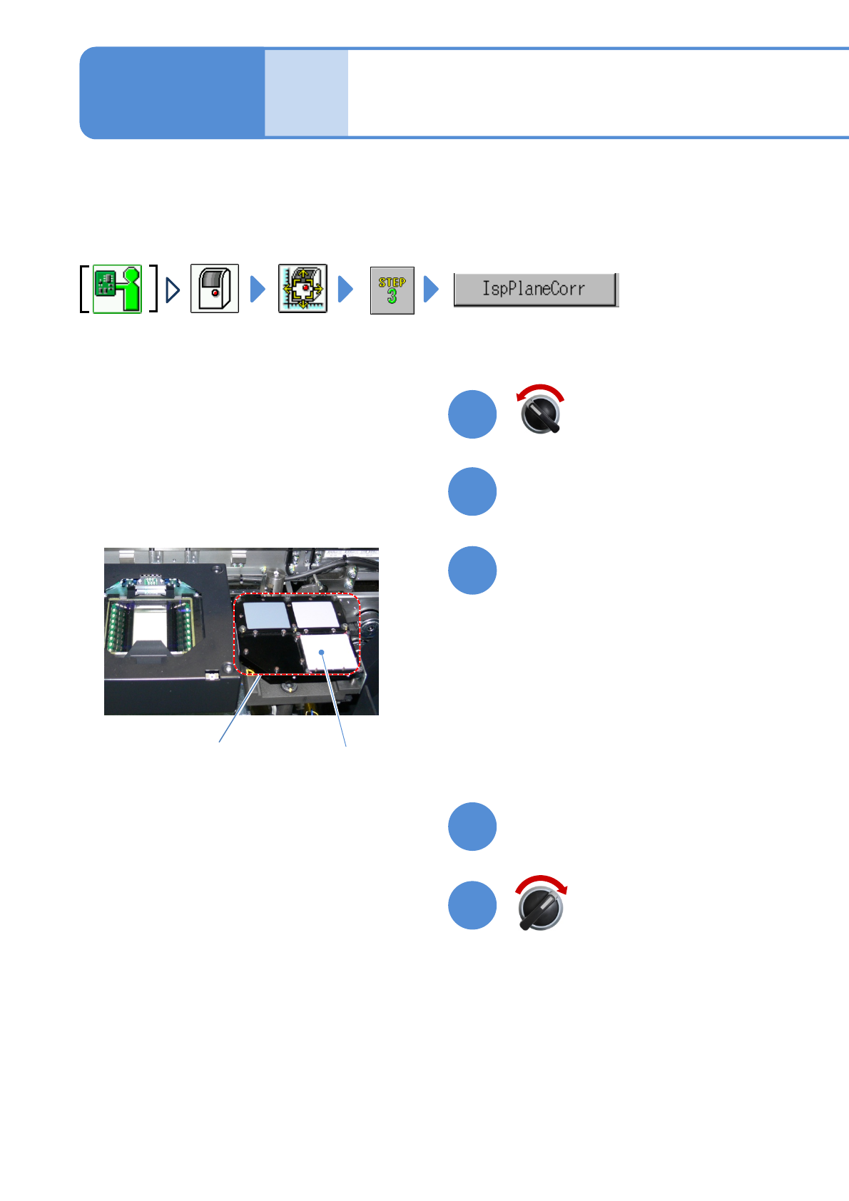
Check a calibration jig and a
distortion correction plate
Close the safety cover
Open the safety cover
Servo switch ON
Servo switch OFF
Distortion correction plate
Calibration jig
●When calibration is carried out, make
sure that the calibration jig is securely
tightened and the distortion correction
plate is not dirty. If it is dirty, clean it
with a blower brush.
NPM-W2 EJM7DE-MB-13M-00
13-16-2
6
7
8
Choose a table
+
6
8
(The head operates to measure the
distortion)
Confirm that it has been
successfully completed
Calibration
7
●If an error occurs, check if the
distortion correction plate is dirty. If it
is dirty, clean it with a blower brush
and then try making measurement
again.
●If you fail to correct the error with the
above method, contact us.
NPM-W2 EJM7DE-MB-13M-00
Inspection plane
correction
(2D inspection head)
13-17-1
Maintenance
13-17
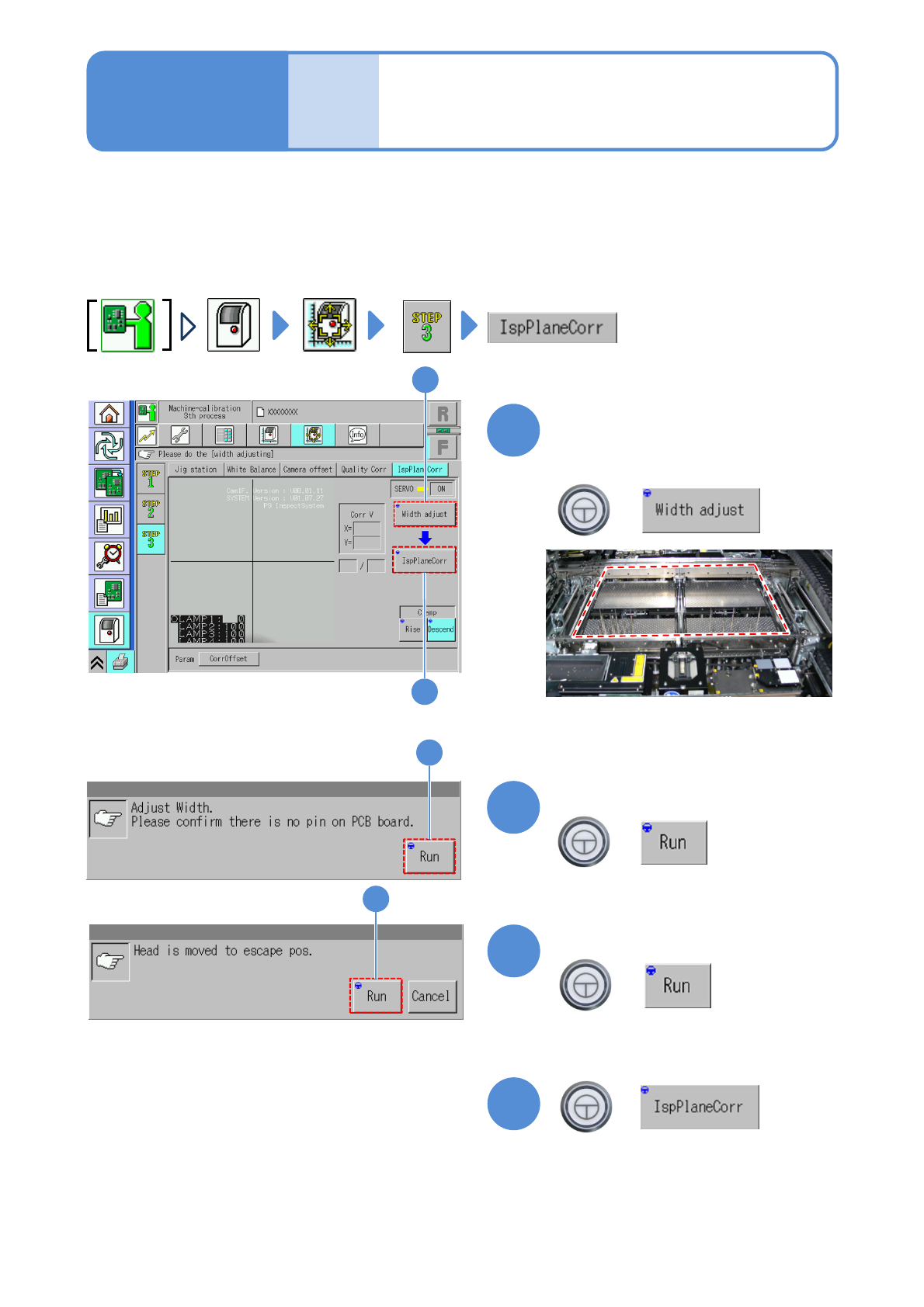
This operation is calibration for the inspection head.
Because the plate correction jig will be manually installed, adjust the transport conveyor width on the pre/post
process machines to the plane correction jig width.
●Remove all support pins before calibration.
●This operation must perform together with plane correction XY in STEP 1.
●After this, the same procedure in
STEP 1, Plane correction XY 1
(→P.13-3) applies.
+
+
1
2
+
3
+
4
Check that there are no PCBs
and support pins present
inside the machine
●If ‘error’ message appears, remove all
the PCBs remaining inside the machine,
and try again.
(The conveyor width is adjusted to the
plane correction jig width)
Confirm the message
(The head moves to the retraction
position.)
Confirm the message
(Press the button to start measurement)
2
1
3
4