N7201A617E00_0317.pdf - 第45页
NPM-W 2 EJM7DE-SF-01N-0 0 1-2 -18 Confirmation ■ Independent changeover corresponding unit Front side Rear side ● It is attached on the back of the movable cover. ● It is attached on the back of the movable cover.
NPM-W2 EJM7DE-SF-01N-00
1-2-17
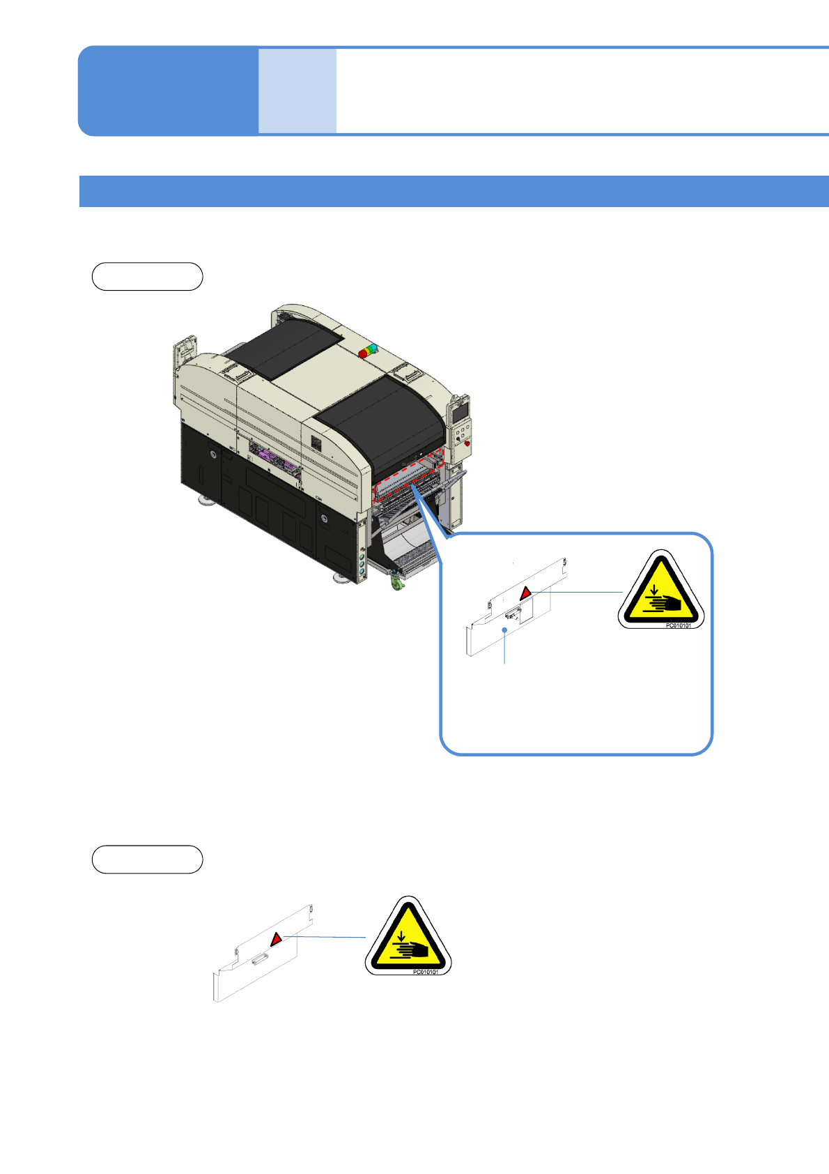
Warning labels 9
1-2
Warning labels
■Safety cover
Safety cover
Front side
Rear side
●Dispensing head specification
●2D inspection head specification
●Non-head specification
●Dispensing head specification
●Non-head specification
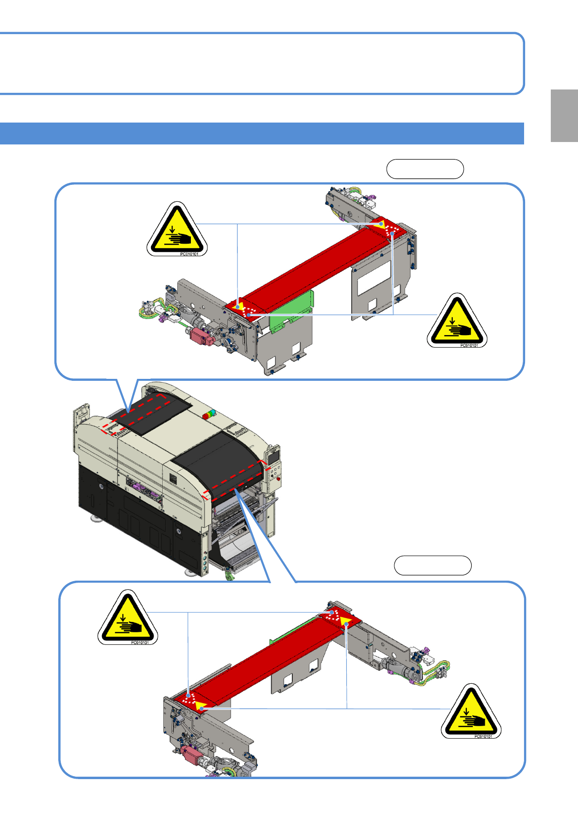
NPM-W2 EJM7DE-SF-01N-00
1-2-18
Confirmation
■Independent changeover corresponding unit
Front side
Rear side
●It is attached on the back
of the movable cover.
●It is attached on the
back of the movable
cover.
NPM-W2 EJM7DE-SF-01N-00
Safety
manage-
ment
Safety switches /
Key management /
Maintenance placard
1-3-1-1
Safety switches
Key management
Safety covers on the machine are equipped with safety switches. In the event that either front or rear of the
safety cover is opened accidentally during automatic production, the machine will come to an emergency
stop to ensure the safety of the operators.
When you encounter a section in the manuals that reads [Turn off the main power supply as well as
stopping air supply], a lock is needed. The key for the lock should be managed by a trained person,
according to the customer’s management standard.
4
3
2
1
5
Safety covers
●Before starting automatic production, ensure that all safety covers are closed.
●When material replenishment is needed, a message will be displayed on the screen instructing you which
corresponding cover can be opened to replenish the materials.
Servo Switch
●When working inside the machine like performing changeovers or maintenance tasks, be sure to turn OFF
the servo switch on the side that is being worked on to ensure operator safety.
●If the servo switch is turned OFF, all axes will be disabled.
●Before starting production, verify whether the servo switches on the front and rear control panel have been
turned ON.
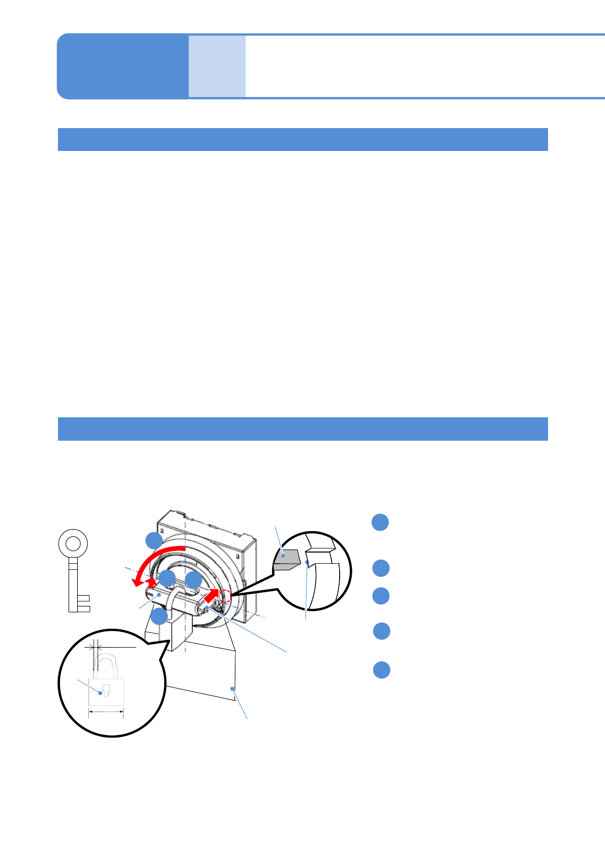
■Locking/Unlocking procedure
Rotate the knob to left to the position
where marks on the lock plate and the
case match.
Push in the lock plate.
Turn the knob to [OFF] position with
holding the lock plate.
Put the padlock through the center
hole to lock.
Place the maintenance placard
indicating maintenance work in
progress.
1-3-1
4
2
1
3
Knob
Lock plate
Placard
key
30 to 50 mm
φ5 to φ8
Lock
Lock plate
Mark on the
case