N7201A617E00_0317.pdf - 第465页
NPM-W 2 EJM7DE-MB-13M-00 13-21-1 -6 Calibration The MCDATA (Production progra m) is contained in the DVD-ROM (Machin e system /Recognition / LNB system disk) that comes with the machine. Refer to the MCDATA sheet incl ud…
NPM-W2 EJM7DE-MB-13M-00
MCDATA (Production program)
●There are four head types: Light weight 16-nozzle, 12-nozzle, 8-nozzle, and 2-nozzle.
●The supply section is on the front: feeder only, on the rear: feeder (F), single tray (FT)
*4)
or twin tray
feeder(TT).
●In the head pattern, for example, 8-8F shows the front: 8 nozzles, the rear: 8 nozzles, feeder-supply
section. Likewise, 3-3FT shows the front: 3 nozzles, the rear: 3 nozzles, single tray-supply section.
●For the machine equipped with the light weight 16-nozzle head, the 12-nozzle head, and the 8-nozzle head,
both heads are used for efficiency.
●Combinations other than listed here include combined use with ‘without head’ and a dispensing or
inspection head.
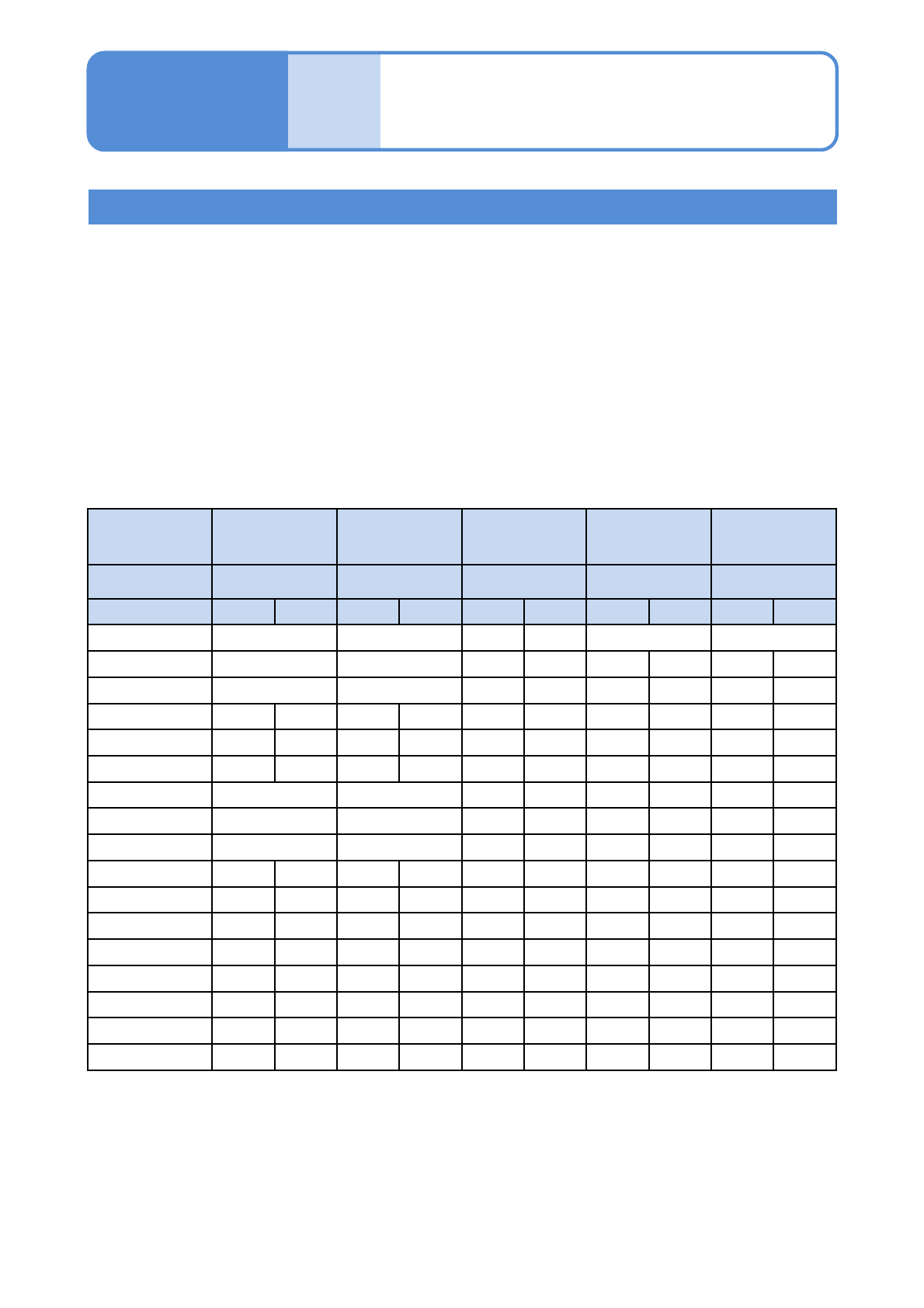
The table below is the major configuration of heads and supply sections.
(example of major configuration)
○ : Placing by front and rear heads
Head designation: Placing by designated head only
13-21-1-5
Maintenance
13-21-1
Accuracy
verifica-
tion
Overview 3
(placement head)
Offset Chip Micro General-purpose
For ±0.025 mm
(option)
For 03015
placement
(option)
*3)
Component to
use
1005Jig chip 0402R JIG_BGA 1005Jig chip 03015R
Head pattern Front Rear Front Rear Front Rear Front Rear Front Rear
LW16-LW16F --- ---
LW16-12F --- --- LW16 --- LW16 ---
LW16-8F --- 8 LW16 --- LW16 ---
LW16-3F LW16 (3)
1)
LW16 --- --- 3 LW16 --- LW16 ---
LW16-8FT(TT) LW16 (8)
2)
LW16 (8)
2)
--- 8 LW16 --- LW16 ---
LW16-3FT(TT) LW16 (3)
1)
LW16 --- --- 3 LW16 --- LW16 ---
12-12F --- --- --- --- --- ---
12-8F --- 8 --- --- --- ---
8-8F 8 8 --- --- --- ---
12-3F 12 (3)
1)
12 --- --- 3 --- --- --- ---
8-3F 8 (3)
1)
8 --- 8 3 --- --- --- ---
3-3F (3)
1)
(3)
1)
--- --- 3 3 --- --- --- ---
12-3FT(TT) 12 (3)
1)
12 --- --- 3 --- --- --- ---
8-3FT(TT) 8
1)
(3)
1)
8 --- 8 3 --- --- --- ---
3-3FT(TT) (3) (3)
1)
--- --- 3 3 --- --- --- ---
12-8FT(TT) 12 (8)
2)
12 (8)
2)
--- 8 --- --- --- ---
8-8FT(TT) 8 (8)
2)
8(8)
2)
8 8 --- --- --- ---
LW16: Light weight 16-nozzle head
F: Tape feeder specifications
FT: Single tray feeder specifications
*4)
TT: Twin tray feeder specifications
1) Perform when the chip is picked up with the 3-nozzle head, except for the twin tray (TT).
2) Perform when the 8-nozzle head chip (0603 or over) or 0402 is picked up, except for the twin tray (TT).
3) Use micro (0402R) MCDATA for registering each-position-angle offset for 03015 component.
4) Specifications with 13-slot supply unit and single tray feeder installed.

NPM-W2 EJM7DE-MB-13M-00
13-21-1-6
Calibration
The MCDATA (Production program) is contained in the DVD-ROM (Machine system /Recognition / LNB
system disk) that comes with the machine.
Refer to the MCDATA sheet included in the DVD-ROM, select the target MCDATA according to the machine
type. Copy it to an SD card once and load it to the machine.
An SD card should be prepared by the customer.
If you overwrite the MCDATA downloaded to the machine to the SD card, the MCDATA in the SD card will not
be functioned. If you accidentally overwrite to the SD card, copy the data from DVD-ROM again.
If you must perform accuracy verification by the configuration which is not in the MCDATA list such as head
change, please contact us.
NOTICE

NPM-W2 EJM7DE-MB-13M-00
Overview 4
(Inspection head)
Maintenance
13-21-1
Accuracy
verifica-
tion
Accuracy verification
Explains considerations for accuracy verification.
■MCDATA type
MCDATA (production program) is exclusively used for accuracy verifications.
There are the following two types of MCDATA used for inspection accuracy verifications.
Offset Refection MCDATA
*The one with “TSEIDO” included
in its data name
The inspection head inspects a circle of 2mm diameter on the plane
calibration jig and measures a displacement amount between the
design coordinates and the actual coordinates.
It is used when inspection camera offset acquired from the measured
result is reflected to the inspection head.
Accuracy Verification MCDATA
*The one with “SKEN” included in
its data name
The inspection head inspects the part patterns on the plane calibration
jig and measures a displacement amount between the design
coordinates and the actual coordinates.
MCDATA filename
W2 - I09 - ALL - SKEN - L1*** - B510
①
②
③④ ⑤
①
Machine name
W2 (NPM-W2)
②
Head
configuration
L16: light weight 16-nozzle / M12: 12-nozzle / M08: 8-nozzle / M03: 3-nozzle / NON:
without heads / I18:Inspection head 18 μm / I09: Inspection head 9 μm / D02:
dispensing head / ALL(all head):This is used when only inspection head is verified,
and the type of the diagonal head is not considered
③
Mode TSEIDO: for offset reflection use / SKEN: for accuracy verification use
④
Lane
L1: Lane 1
* *** area (Only “SKEN” is included in the data name)
SL: Two points PCB recognition / SS: Pattern recognition
(If ‘R’ is included in the rear side, it is the first placement position and for ‘L’, it is the
second placement position)
⑤
PCB size (If “REV” is included before the PCB size, it is MCDATA for right to left flow)
13-21-1-7