N7201A617E00_0317.pdf - 第466页
NPM-W 2 EJM7DE-MB-13M-00 Ov er view 4 (Inspection head) Maintenance 13-21-1 Accuracy verifica- tion Accuracy verification Explains consideration s for accuracy verification. ■ MCDA T A type MCDATA (productio n progra m) …

NPM-W2 EJM7DE-MB-13M-00
13-21-1-6
Calibration
The MCDATA (Production program) is contained in the DVD-ROM (Machine system /Recognition / LNB
system disk) that comes with the machine.
Refer to the MCDATA sheet included in the DVD-ROM, select the target MCDATA according to the machine
type. Copy it to an SD card once and load it to the machine.
An SD card should be prepared by the customer.
If you overwrite the MCDATA downloaded to the machine to the SD card, the MCDATA in the SD card will not
be functioned. If you accidentally overwrite to the SD card, copy the data from DVD-ROM again.
If you must perform accuracy verification by the configuration which is not in the MCDATA list such as head
change, please contact us.
NOTICE

NPM-W2 EJM7DE-MB-13M-00
Overview 4
(Inspection head)
Maintenance
13-21-1
Accuracy
verifica-
tion
Accuracy verification
Explains considerations for accuracy verification.
■MCDATA type
MCDATA (production program) is exclusively used for accuracy verifications.
There are the following two types of MCDATA used for inspection accuracy verifications.
Offset Refection MCDATA
*The one with “TSEIDO” included
in its data name
The inspection head inspects a circle of 2mm diameter on the plane
calibration jig and measures a displacement amount between the
design coordinates and the actual coordinates.
It is used when inspection camera offset acquired from the measured
result is reflected to the inspection head.
Accuracy Verification MCDATA
*The one with “SKEN” included in
its data name
The inspection head inspects the part patterns on the plane calibration
jig and measures a displacement amount between the design
coordinates and the actual coordinates.
MCDATA filename
W2 - I09 - ALL - SKEN - L1*** - B510
①
②
③④ ⑤
①
Machine name
W2 (NPM-W2)
②
Head
configuration
L16: light weight 16-nozzle / M12: 12-nozzle / M08: 8-nozzle / M03: 3-nozzle / NON:
without heads / I18:Inspection head 18 μm / I09: Inspection head 9 μm / D02:
dispensing head / ALL(all head):This is used when only inspection head is verified,
and the type of the diagonal head is not considered
③
Mode TSEIDO: for offset reflection use / SKEN: for accuracy verification use
④
Lane
L1: Lane 1
* *** area (Only “SKEN” is included in the data name)
SL: Two points PCB recognition / SS: Pattern recognition
(If ‘R’ is included in the rear side, it is the first placement position and for ‘L’, it is the
second placement position)
⑤
PCB size (If “REV” is included before the PCB size, it is MCDATA for right to left flow)
13-21-1-7
NPM-W2 EJM7DE-MB-13M-00
13-21-1-8
Brief description of process
This section describes the procedures for measuring the inspection head accuracy and updating the
inspection camera offset by using the measured result. The plane correction jig is used for
measurement.
●Because the plane correction jig is inserted and taken out from the upstream process, adjust the
width of the upstream transfer conveyor to that of the plane correction jig.
The dedicated MCDATA (production
program) is used for inspection head
accuracy verification and registering the
inspection camera offset. When the
inspection camera offset is reflected,
machine parameters in the machine will
be rewritten.
●You are recommended to save the
current data beforehand just in case.
(→[Operating procedure] P.2-3-4)
MCDATA (production program)
●There are two inspection head types: 18 μm and 9 μm.
●If the inspection head is attached, the supply unit is only on the rear side.
Front: Inspection BOX(I)
Rear: Tape feeder (F), single tray feeder (FT)
*1)
or twin tray feeder (TT)
● In the head pattern, for example, 9I-8F shows the front: 9 μm inspection head, the rear: 8- nozzle head,
and the tape feeder supply section.
Likewise, 18I-3FT shows the front: 18 μm inspection head, the rear: 3- nozzle head, and the single tray
feeder supply section
*1)
.
Placement head accuracy
verification
Head pattern
9I-LW16F 18I-LW16F
9I-12F 18I-12F
9I-8F 18I-8F
9I-3F 18I-3F
9I-8FT(TT) 18I-8FT(TT)
9I-3FT(TT) 18I-3FT(TT)
9I-8FT(TT) 18I-8FT(TT)
9I-3FT(TT) 18I-3FT(TT)
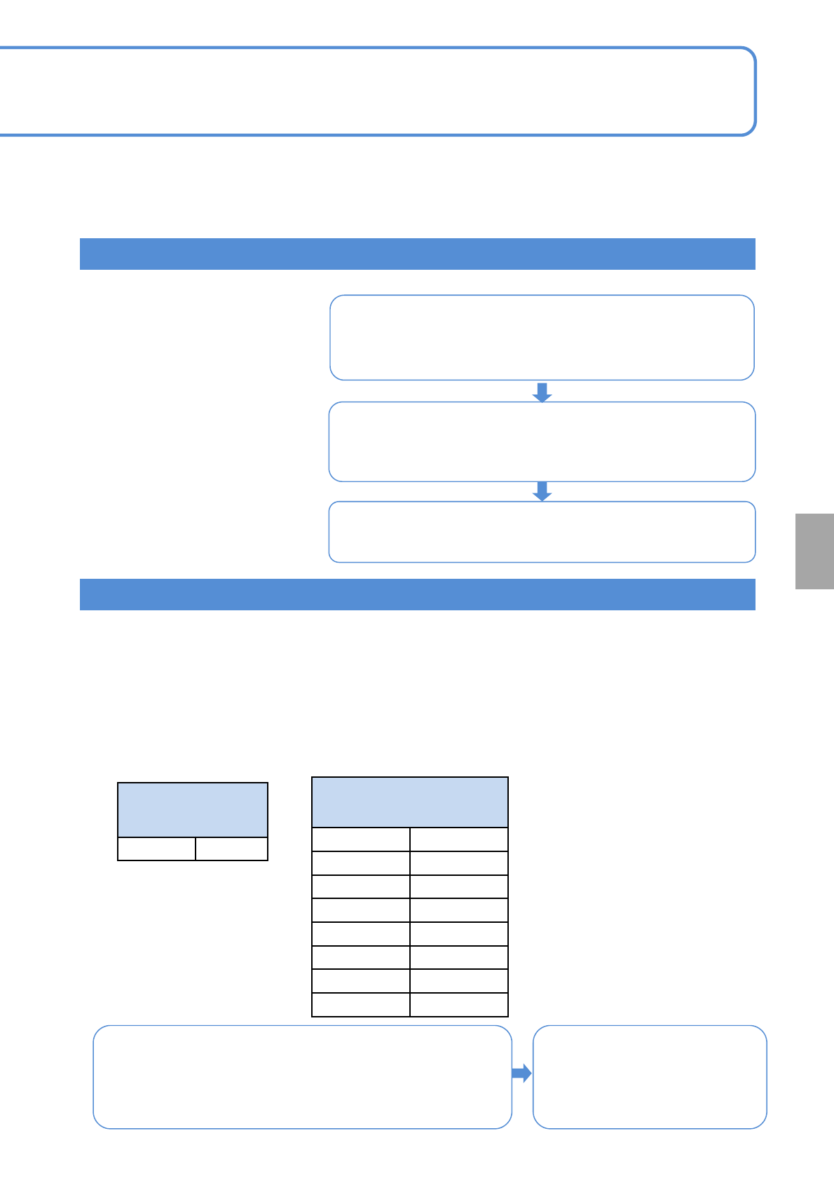
■The table below is the major configuration of heads and supply sections
1.Production
preparation
・Saving calibration DATA (DVD-ROM) to an
SD card
・Setting up the plane correction jig
・Setting production operation
■Working process
3.Confirmation of
accuracy
verification result
・Selection of MCDATA (Production program)
・Measurement
・Checking of measurement results
2.Check and
reflection of
measurement
(offset registration)
・Selection of MCDATA (Production program)
・Measurement
・Checking and reflection of placement results
LW16: Light weight 16-nozzle head
F: Tape feeder specifications
FT: Single tray feeder specifications
*1)
TT: Twin tray feeder specifications
Except ALL on the rear side:
Verify placement accuracy
(→P.13-21-1-1)
Calibration
Head pattern in case
of inspection head
accuracy verification
9I-ALL 18I-ALL
ALL on the rear side:
Verify accuracy of the
inspection head
■Verification order
2D inspection head
① First placement position: Offset reflection MCDATA
② First placement position: Accuracy check MCDATA
③ Second placement position: Accuracy check MCDATA
Inspection head
①Calibration STEP2 to STEP4
(→ P13-1-2)
②Accuracy verification
(→ P13-21-1)
) Specifications with the 13-slot
supply unit and the single tray
feeder installed.