N7201A617E00_0317.pdf - 第471页
NPM-W 2 EJM7DE-MB-13 M-00 2 1 To Set the nozzles to the nozzle holders (This task is the same as the normal production operation) Place components 13-21-2 -2 3 ■ For chip or micro ■ When JIG_BGA, supply stage is put on t…
NPM-W2 EJM7DE-MB-13M-00
Accuracy
verifica-
tion
13-21-2-1
Maintenance
13-21-2
2
1
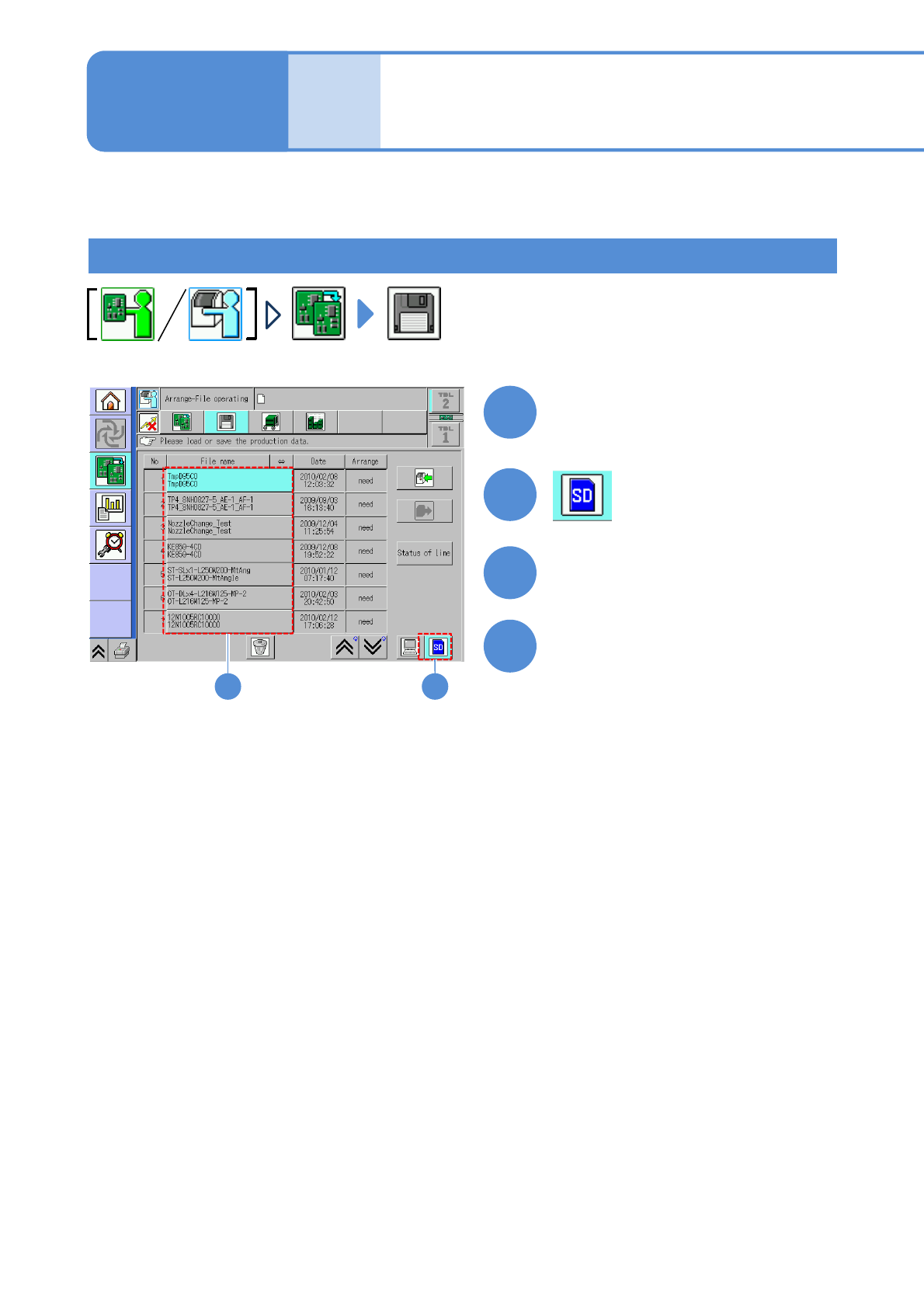
Production preparation 1 (Loading MCDATA: Production program)
23
Set the SD card which MCDATA
has been copied
3
●Load the data as same way as the
normal production data.
4
Choose MCDATA
Load MCDATA
Detailed process 1
(placement head)
(→ P.13-21-1-1 ‘■MCDATA type’)
About accuracy verification of the machine with a combination of the placement head and the inspection
head, see P.13-21-2
-9.
About accuracy verification of the machine with a combination of the placement head and the dispensing
head, see P.13-21-1
-17.
NPM-W2 EJM7DE-MB-13M-00
2
1
To
Set the nozzles
to the nozzle
holders
(This task is the same as
the normal production
operation)
Place components
13-21-2-2
3
■For chip or micro
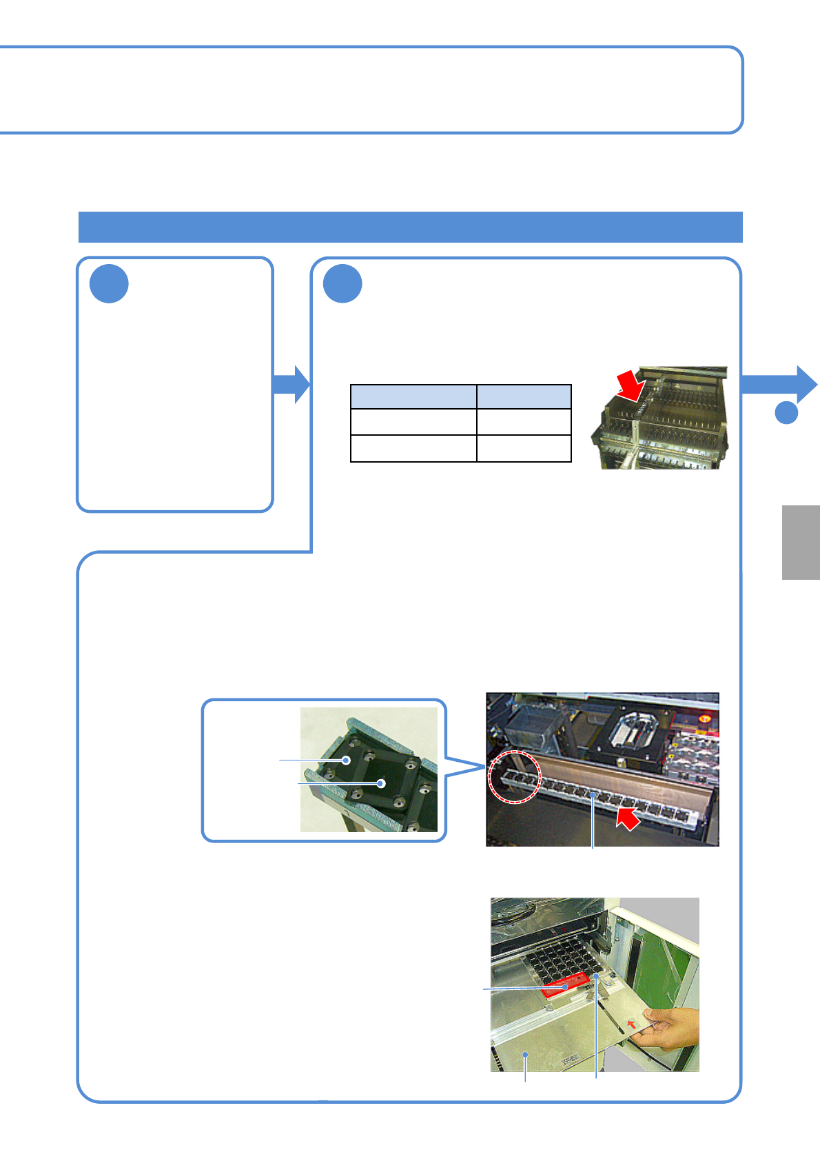
■When JIG_BGA, supply stage is put on the feeder cart
First stage
Second stage
Tray (storage aluminum case)
Tray pallet
Remove JIG_BGA (N610087876AA) from the tray and set it to the supply stage (N610074266AA).
●Left-align (Z1 to Z17) and install the supply stage.
●Install it in a line to prevent JIG_BGA from slanting.
●The supply stage consisting of two stages can be installed with 16 JIG_BGAs x 2 stages.
■ When JIG_BGA is put on the tray feeder
Calibration
Supply stage
●Set 1005JIG chip or 0402R to the tape feeder and install it to
the following slot.
Supply unit Slot No.
Feeder cart No.5
13-slot feeder
No.24
Production preparation 2 (preparation for verification material )
●When placement is performed on the both heads (front and
rear), set the feeder on the front and rear sides.
●You should perform teaching of the pockets in the tape feeder
where appropriate.
(This task is the same as the normal production operation)
①Install components together with the tray (storage
aluminum case) to the tray pallet.
②Set a tray pallet to slot 1 on the tape feeder.
(This task is the same as the normal production operation)
●Right-align and set the tray (storage aluminum case) in the
back as seen from the rear.
●Pay attention to the installation orientation.
JIG_BGA itself has no particular orientation. However, do
not place any parts onto four boxes in the section A in the
picture on the right side.
●For the twin tray feeder, set it to slot 1 on the tray A side.
A section
NPM-W2 EJM7DE-MB-13M-00
13-21-2-3
Accuracy
verifica-
tion
3
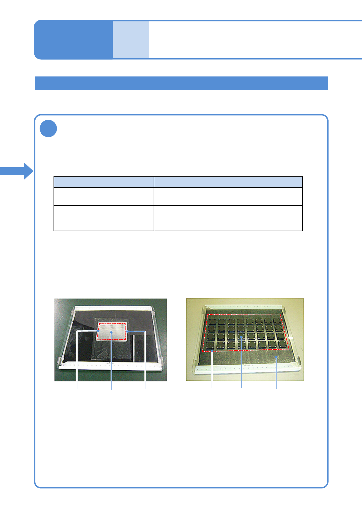
Prepare the glass PCB
Glass PCB after 1005JIG chip are placed
Glass PCB after JIG_BGA are placed
Production preparation 3 (preparation for verification material )
①Prepare a glass PCB set (N610108752AA) for placement accuracy check.
(Glass PCB, background plate and mirror are included)
Part Background
JIG_BGA Black sponge
(Set the background plate)
1005JIG chip: ERJJ02AAAAAV,
0402R, etc.
Insert a mirror between the glass and the
background plate.
(See the manual included in the glass PCB set)
1005JIG
chip
●Affix the tape to the area where components are placed (Inside the dotted line in the picture
below is a rough area)
●Keep away from recognition marks on the both edges of the glass.
●Affix the tape with no air bubbles.
②Prepare the background based on a component to verify its accuracy.
③Affix the double-faced tape onto the glass PCB.
MirrorPlacement
area
JIG_BGAPlacement
area
Background plate
(black sponge)
Detailed process 2
(placement head)
Maintenance
13-21-2