N7201A617E00_0317.pdf - 第478页
NPM-W 2 EJM7DE-MB-13M-00 2 1 Production preparation 1 (Loadi ng MCDA T A: Production program) 2 3 Set the SD card which MCDA T A has been copied 3 4 Detailed pr ocess 5 (inspection head) Maintenance 13-21-2 13-21-2 -9 Ac…

NPM-W2 EJM7DE-MB-13M-00
13-21-2-8
Checking of placement result
Cause Troubleshooting
The target components are deteriorated
Check for any flaws or foreign bodies on the
surface of JIG_BGA.
The correct jig parts are not used. Check the jig parts.
Actual parts 1005C are used. Check the jig parts.
The head shaft is damaged Check for unsmooth sliding of the shaft.
The illumination of the multi-recognition
camera is wrong.
Execute the lamp-value illumination calibration.
Calibration
●If you perform above measures, but the accuracy verification result is not improved or you find any trouble
on the head shaft, please contact us.
Verifies the results registered as offsets in “Checking and reflection of placement.” The procedure is the
same as the one used in “Checking and reflection of placement.”
Though not necessarily required, this procedure will be used as a guideline for measuring the level of
accuracy of the machine.
●As for MCDATA (production program), use accuracy verification MCDATA.
(→ P.13-21-1
-1 ’■MCDATA type’)
●Accuracy verification MCDATA is intended for accuracy verification use, so refrain from reflecting in it the
each-position-angle offsets obtained from measurement results.
(→ P.13-21-1
-1 ‘■Reflection of verification data’)
The following causes are cited as possible causes when no improvements are seen in accuracy verification
results.
NPM-W2 EJM7DE-MB-13M-00
2
1
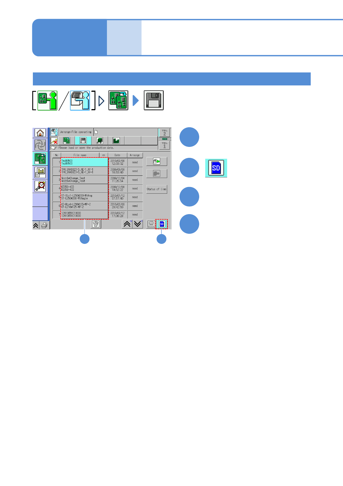
Production preparation 1 (Loading MCDATA: Production program)
23
Set the SD card which MCDATA
has been copied
3
4
Detailed process 5
(inspection head)
Maintenance
13-21-2
13-21-2-9
Accuracy
verifica-
tion
Choose MCDATA
Load MCDATA
(→ P.13-21-1-7 ‘■MCDATA type’)
●Load the data as same way as the
normal production data.
●If you cannot load MCDATA, set the
machine number to the first machine
and load again.
NPM-W2 EJM7DE-MB-13M-00
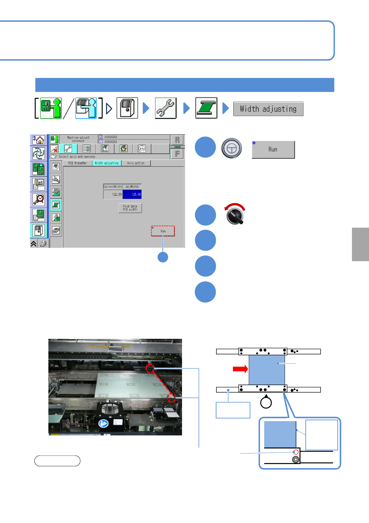
Production preparation 2 (preparation for verification material )
1
1
The width of the transfer conveyor is
adjusted to that of the plane correction jig.
+
Open the safety cover
3
2
Insert the plane correction jig
from the upstream process
4
13-21-2-10
Servo switch OFF
Calibration
5
Set the plane correction jig
②Set FIXED RAIL SIDE(TYPE A) of the
plane correction jig to the reference rail
side.
③Press the jig against the reference rail.
●In case of dual lane mode, change to
the single lane mode.
(→ P.11-3-1)
■When setting to the first placement position
Plane correction
jig
Operator
①
Reference
rail
FIXED RAIL
SIDE(TYPE A)
Plane
correction
jig
Right edge
of plane
correction
Jig
Reference hole
(φ1mm)
①Align and set the edge of the plane
correction jig to each reference hole in
the first or second placement positions
defined by the production data.
(Common to both the left-to-right and
right-to-left flows.)
NOTICE
●The reference hole for the plane correction differs
from the one for accuracy verification. Be sure to
use the correct one.