N7201A617E00_0317.pdf - 第495页
NPM-W 2 EJM7DE-MB-14M-00 T r anspor ta t ion 14-2 Maintenance 14-2 Using a forklift or a pallet truck Keep turning the Adjustme nt bolt’s adjustmen t bolt until the bottom of the machine is raised higher than the forks. …
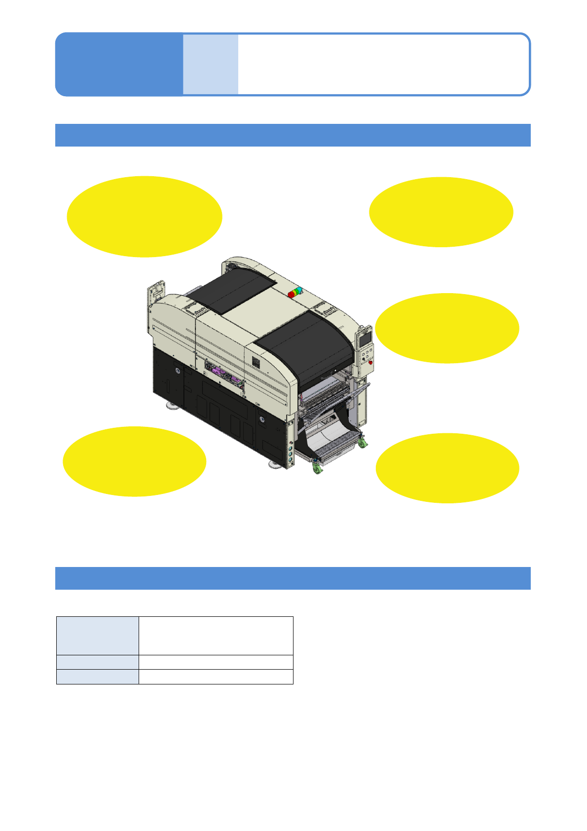
NPM-W2 EJM7DE-MB-14M-00
Before installation
■Primary power supply
14-1
Maintenance
14-1
Condensation
free environment
●Temperature: 10 to 35℃
●Humidity: 25 to 75 %RH
Adequate space
for maintenance
work
Draw a layout
baseline on the
floor
■Air source
●Use clean air provided by an air dryer.
●Air pressure: 0.5 to 0.8 MPa
After air is supplied, adjust the air pressure to
0.500 to 0.505 MPa with the regulator.
●Amount of air supply: 200 L/min(A.N.R)
●Hose connection inlet size: 3/8 inch
Flat concrete
floor
●Withstand load of the
installation place:
4903 N/m
2
or higher
●Supply from power equipment managed by the plant.
(Public low-voltage power distribution system: Do
not connect directly to the commercial power supply)
Normal power
supply
3-phase AC 200 ±10 V/ 220
±10 V
380/400/420/480 ±20 V
Frequency
50 / 60 Hz ±5%
Rated capacity 2.8 kVA
Checking installation location
Check primary power supply and air source specifications
● [Outside dimensions] (→[Operating procedure] P.9-1-3), [Altitude] (→[Operating procedure] P.9-1-1)
Flat place
●PCB transfer height: 900 to
920 mm (Both single and line
connection)
NPM-W2 EJM7DE-MB-14M-00
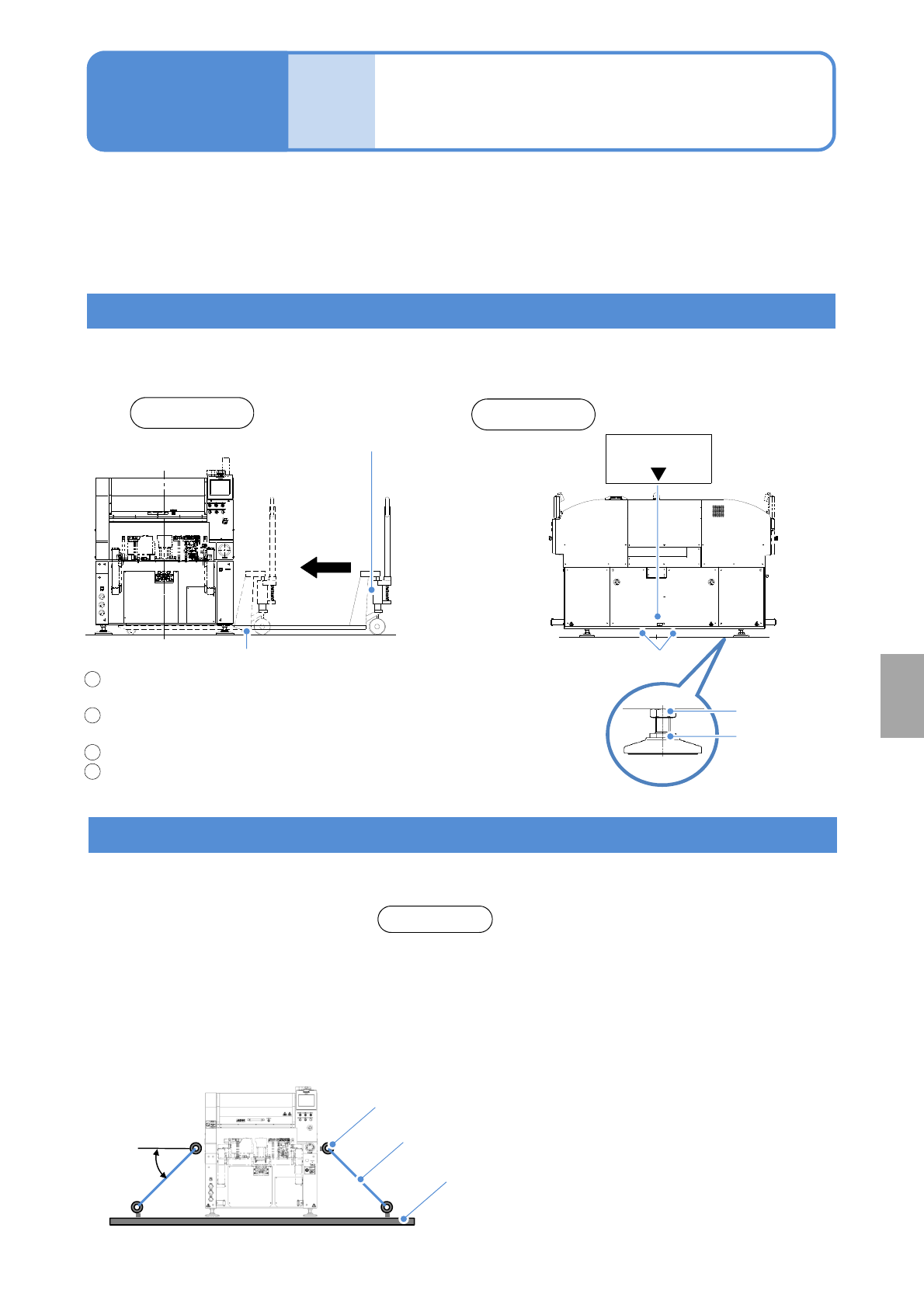
Transportation
14-2
Maintenance
14-2
Using a forklift or a pallet truck
Keep turning the Adjustment bolt’s adjustment bolt until
the bottom of the machine is raised higher than the forks.
Insert the forks under the machine from the right side
●Align the center of two forks to ▼ shown on the sticker.
Raise the forks and lift the machine.
Convey the machine to the destination and set it down.
Tool used: 46 mm spanner (2 pcs)
■Fork insertion position
●Insert the forks from the side
Using a crane
1
3
4
Installation
Pallet truck or forklift
Fork insertion position
Forks
Lock nut
Adjustment bolt
Right side
Front side
2
MASS: 2 470 kg
CENTER
Please consult a specialized delivery company.
Eye bolts
(four)
●Use eyebolts for fixing the machine to a cart or others. An angle
θ that the fixing rope makes with a horizontal line should be 45
degrees or less.
●Do not use eyebolts to lift the machine.
●Store eyebolts after transport.
ATTENTION
θ
Fixing rope
Cart
Carefully handle the machine during transportation. When any of the feeder cart, tray feeder, cable or pipe is
connected to the main unit, remove it before transportation.
In addition, for the machine with the extension conveyor installed, the cable attached to the conveyor must be
removed from the machine to prevent it from getting stuck by the fork.
NPM-W2 EJM7DE-MB-14M-00
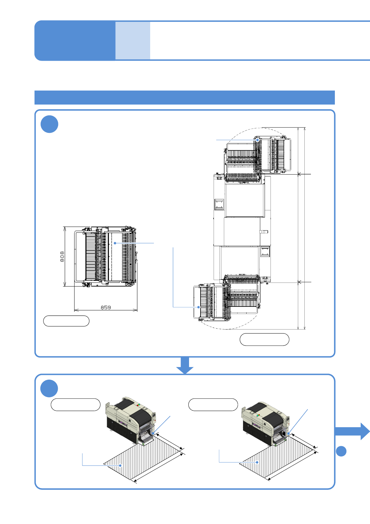
1 080
2 332
1 080
4 492
14-3-1
Temporarily locate the machine along the baseline
drawn on the floor and adjust the installation position.
●Adjust the height and facing of the machine to
guarantee a smooth PCB transfer between the
machine and adjacent equipment in a line.
●Keep a 1 to 5 mm space between the machine
and adjacent equipment.
●If running a vent under the machine, keep a 40
mm or more space between the machine and the
vent.
(The figure on the right shows the minimum space
and is measured in millimeters (mm))
2
Check the working area
Working area
1 080
1 830
Tool used: Convex, Allen wrench (3 mm), metal ruler, Level gauge, 46 mm spanners (2 pcs)
Feeder
cart
Feeder cart
Installation 1
Maintenance
14-3
1 080
1 830
Working area
Front side
Front side: Feeder cart/ Rear side: Feeder cart
Front side Rear side
To
(P.14-3-4)
3
●Regarding installation, follow the instructions of
a specialist.
●Regarding relocation, contact us, please.
NOTICE
1
Install
Coverendface
Coverendface
Cover end
face
Cover end
face