N7201A617E00_0317.pdf - 第507页
NPM-W 2 EJM7DE-MB-14M-00 14-4-3 -2 Change the mac hine voltage. e.g., Changing from 400 V AC to 200 V AC 3 Check the plant supply voltage Remove the cover 4 Easy ways to check power supply grounding (tester confirmation)…
NPM-W2 EJM7DE-MB-14M-00
Main
power
connec-
tion
Adjusting voltages of the
primary power supply and
the machine
14-4-3-1
Maintenance
14-4-3
1
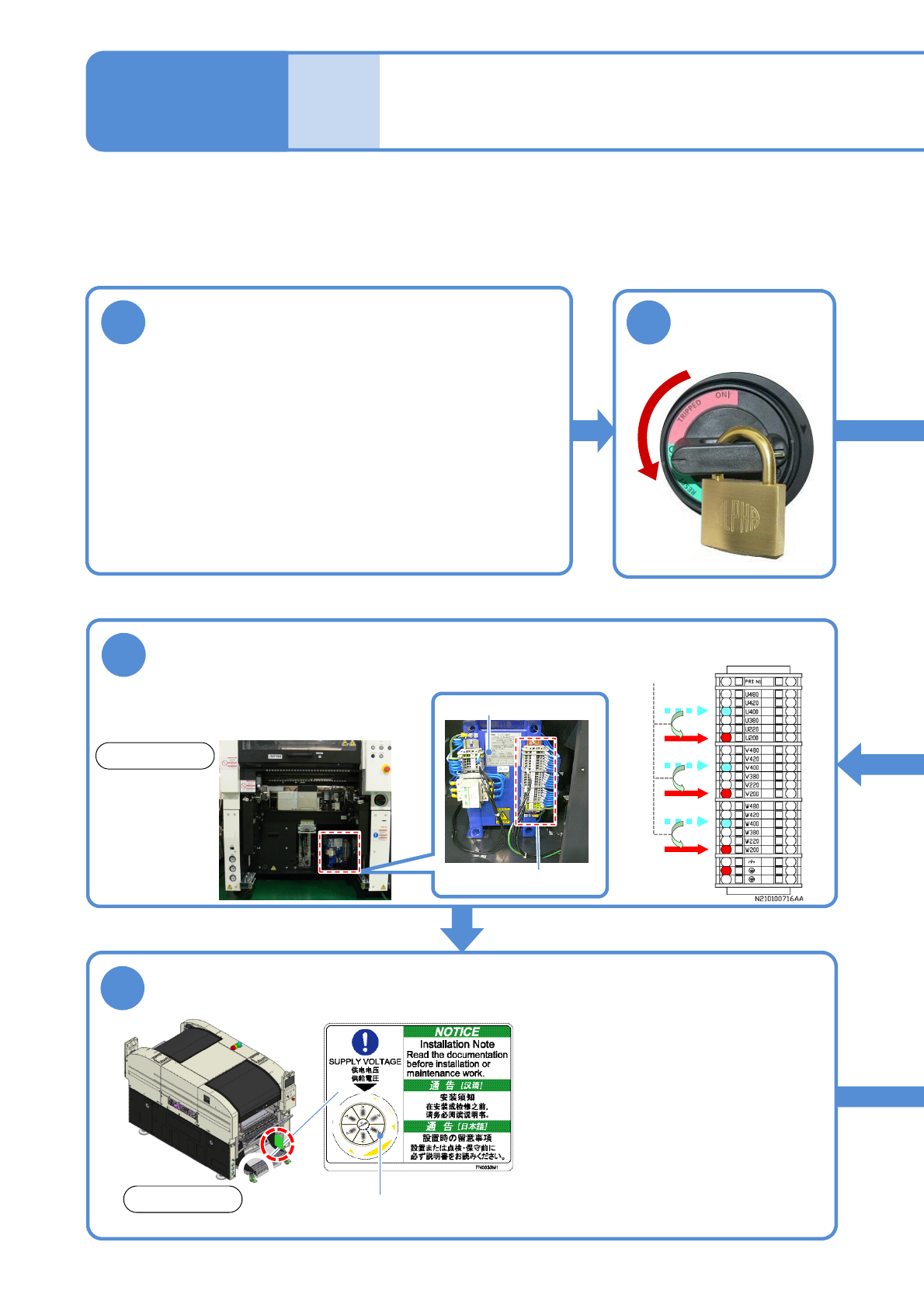
Change the voltage of the primary power
supply
(The primary power supply voltage of the transformer can
be changed to any of the following voltages)
●Adjust it to the voltage of power supply.
Tool used: Allen wrench (4 mm), special driver (provided)
●Before using 290 V AC or higher (any tap equal to or
higher than 380 V AC), ensure that the voltage between
a ground and each phase is 290 V AC or lower and that
star connection is used on the feeding side, with the N
(neutral) terminal connected to the ground.
Adjust the difference in voltage between the primary power supply and the machine, if any.
Attach the cover, and relabel the numerical section of the supply voltage
label
6
●The label indicates the power
supply voltage supplied to the
machine.
When changing the power supply
voltage, purchase a new label and
relabel it.
In that case, align ▼ with the
numeric value on the supply voltage
label that corresponds to the power
supply voltage after the change.
1. 480 V
2. 420 V
3. 400 V
4. 380 V
5. 220 V
6. 200 V
5
Connect U, V, and W to the same voltage taps
(Ex. for AC400 V to 200 V)
●Use the attached special driver to
connect each cable.
Then, insert the ferrules fully.
■Wiring diagrams of transformer
power tap (abstract)
4
2
Turn OFF the
power and lock
the machine
OFF
Change to
Transformer
Numerical section of the
supply voltage label
Front side
Transformer power tap
Front side
NPM-W2 EJM7DE-MB-14M-00
14-4-3-2
Change the machine voltage.
e.g., Changing from 400 V AC to
200 V AC
3
Check the
plant supply
voltage
Remove the
cover
4
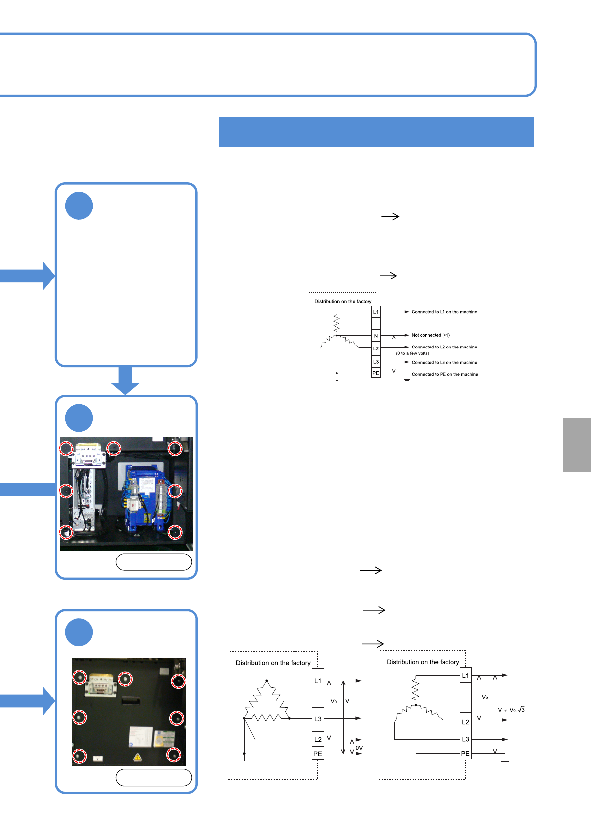
Easy ways to check power supply grounding
(tester confirmation)
■If 5 wires of L1, L2, L3, N and PE are being drawn out
(= star connection) → Measure the voltage between N and
PE
(*1) The neutral wire (N) is not used for the machine. Leave
the cable unconnected to the machine and insulate its
end to keep it from coming in contact with a terminal and
others.
■If 4 wires of L1, L2, L3 and PE are being drawn out, it
can be either star connection or delta connection.
(Usually one phase is grounded on delta connection)
Measure and compare the phase to phase voltage (V
0
)
and the phase to PE voltage (V).
Example 1:
Delta connection grounded
Example 2:
Star connection not grounded
●If the neutral wire is grounded
The value is stable in the
approximate range of 0 to a
few volts.
Connectable at 290 V AC or
higher
●If the neutral wire is not grounded
The value is unstable
(indicates several tens of
volts)
Not connectable at 290 V AC
or higher
●If V = V
0
and V of single phase is 0 V
One phase is grounded on
delta connection
Not connectable at 290 V AC or higher
●If stable at " V
0
/ Square root of 3."
The neutral wire is grounded
on star connection
Connectable at 290 V AC or higher
●If the value is not stable
No ground contact
(Unknown connection type )
Not connectable at 290 V AC or higher
e.g.) Grounded star connection
Installation
●7 bolts
Front side
7
Attach the
cover
●7 bolts
Front side
NPM-W2 EJM7DE-MB-14M-00
Connection of air source
and power supply
Maintenance
14-5
14-5-1
Tool used: Phillips screwdriver (No. 2), Allen wrench (3 mm)
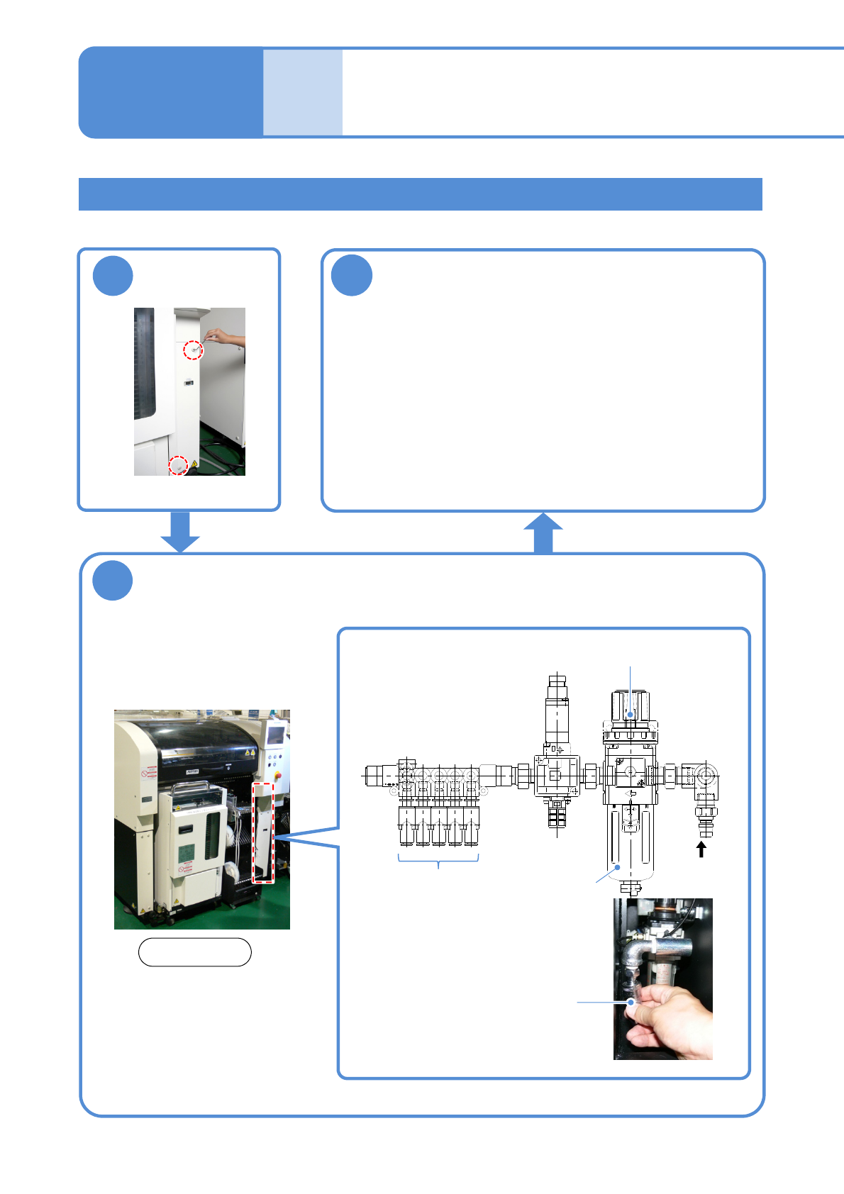
3
Supply air
●Use an air dryer and always supply clean air.
●Air pressure: 0.5 to 0.8 MPa
(The size of the inlet for connecting the hose is 3/8)
●After supplying air, adjust the air pressure to 0.500 to
0.505 MPa with the regulator (→P.4-1-1)
●Air supply rate: 200 L/min (A.N.R.)
2
Connecting air source
1
Remove the
cover
Rear side
●2 bolts
Compressed air piping
(Primary air supply side)
To each
device
A
Filter (inside)
Regulator
Connect the compressed air piping to the
area A in the figure below