N7201A617E00_0317.pdf - 第511页
NPM-W 2 EJM7DE-MB-14M-00 Peripher- al device connec- tion Maintenance 14-6-2 14-6-2 -1 Line signal specifica tions 1 Line signals A sing le cable co nnection is e stablished throughout a line , allowing on e machine in l…
NPM-W2 EJM7DE-MB-14M-00
Peripher-
al device
connec-
tion
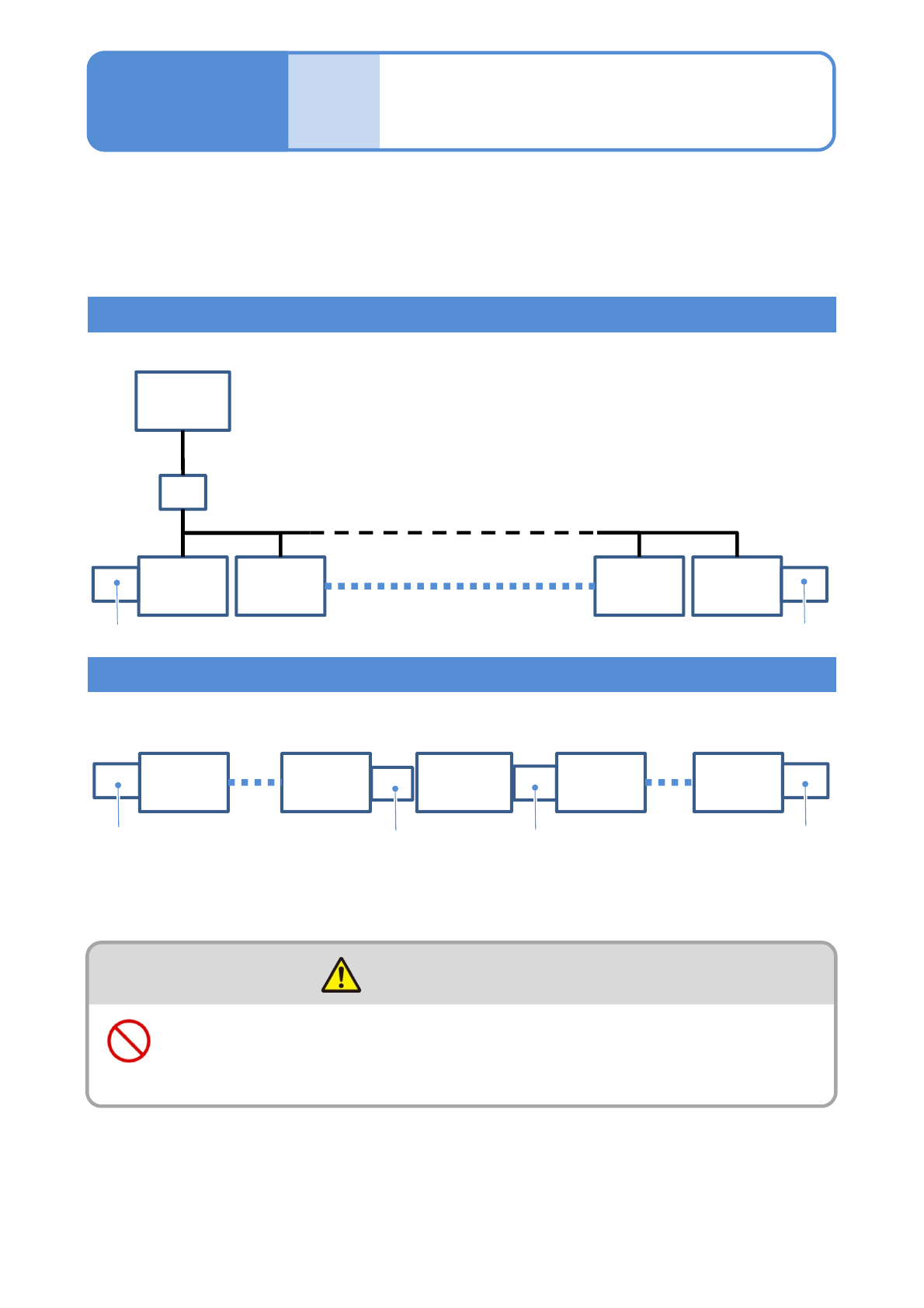
Line configuration
14-6-1
Extension conveyor
This is a sample line configuration, so it can vary depending on your line configuration and
the position of in-line non-NPM.
For details, please contact us.
Line configuration including NPM-W2s only
Line configuration including NPM-W2s and non-NPM-W2
FA
computer
for LNB
HUB
NPM-W2
1
NPM-W2
2
Extension conveyor
NPM-W2
14
NPM-W2
15
Extension conveyor
NPM-W2
1
NPM-W2
Extension conveyor
NPM-W2
NPM-W2
15
Other
than
NPM-W2
Extension conveyor
Extension conveyor
■Up to 15 NPM-W2s can be coupled together
■Up to 15 NPM-W2s can be coupled together
The power supply and the air source must be connected to the
machine after installation of peripheral equipment
(Risk of electric shock or injury)
WARNING
Maintenance
14-6-1
To install NPM-W2 (as a stand-alone unit or in-line), the installation of a unit that functions as an extension
conveyor (option) is required at both ends of the NPM-W2 line.
●Up to 15 NPM-W2s can be coupled together.
When the cable attached to the extension conveyor (optional item specified by us) is not plugged to the
machine, plug it.
NPM-W2 EJM7DE-MB-14M-00
Peripher-
al device
connec-
tion
Maintenance
14-6-2
14-6-2-1
Line signal
specifications 1
Line signals
A single cable connection is established throughout a line, allowing one machine in line to signal it’s
connecting machine to transfer PCBs.
1
2
3
47
8
11
14
13
12
3
2
1
74
11
8
12
13
14
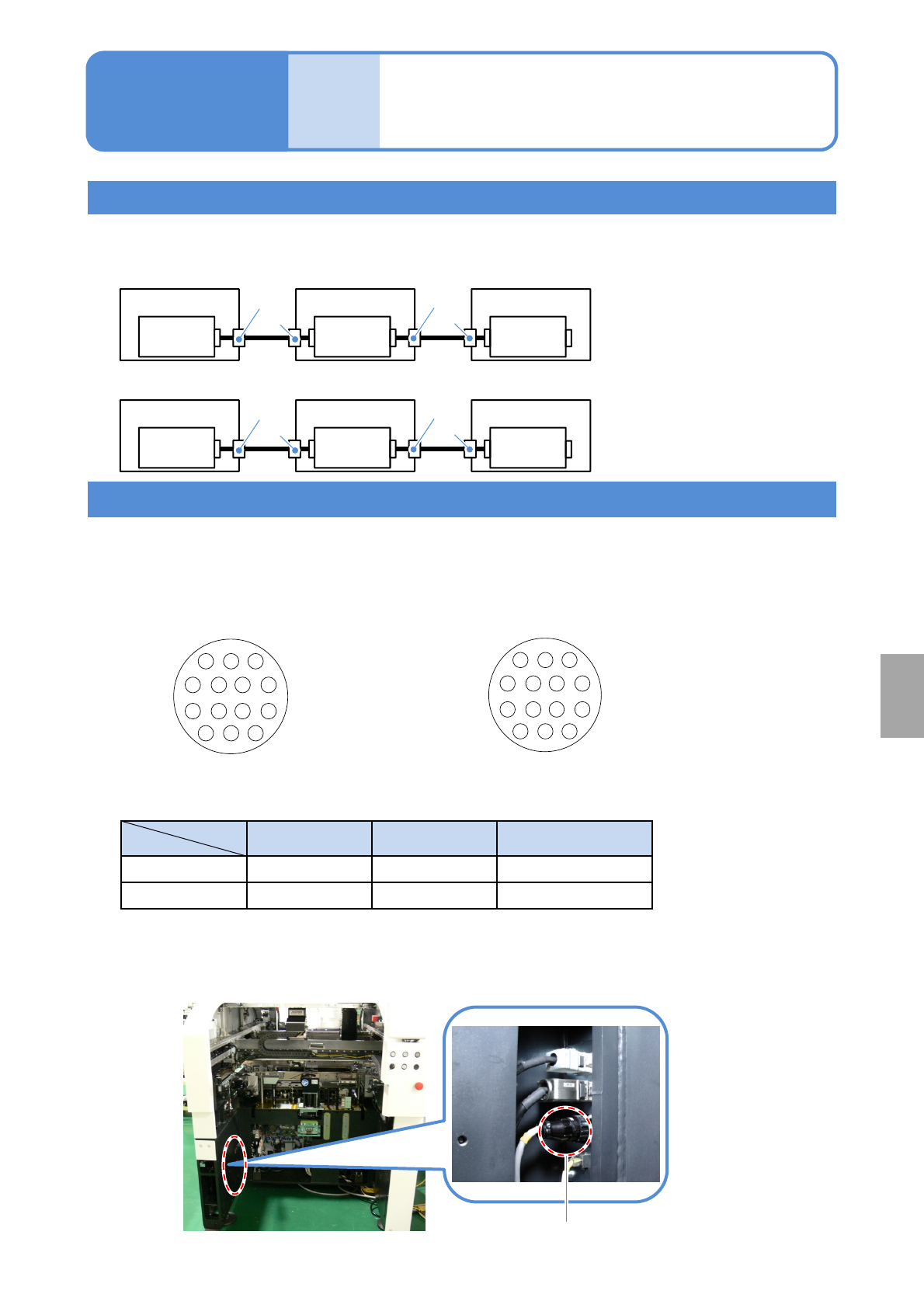
SMEMA connectors are AMP-type connectors for easy connection.
■Connector pin arrangements as seen from the connection ports
Cable-side connector pin arrangement
(Male pins)
Connector Pin Strain relief
Cable side
AMP 206044-1 AMP 66103-2 AMP206070-1
Machine side
AMP 206043-1 AMP 66105-2 -
■Part numbers on the cable and the machine sides
■ SMEMA connector location (one on either side of the rear of the machine)
Arrangement of connector pins
SMEMA connector
Machine-side connector pin arrangement
(Female pins)
-XR
Connector connected to the next
process machine
-XL
Connector connected to the pre-
process machine
■PCB flow direction (From left to right)
Machine 1
Control
Box
Machine 2
Control
Box
Machine 3
Control
Box
■PCB flow direction (From right to left)
Machine 3
Control
Box
Machine 2
Control
Box
Machine 1
Control
Box
Installation
-XL
-XR
-XL
-XR
-XL
-XR
-XL
-XR
NPM-W2 EJM7DE-MB-14M-00
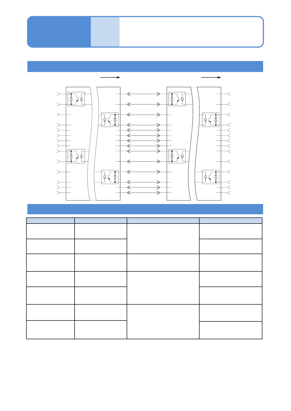
14-6-2-2
Electrical-interface wiring diagram (SMEMA interface)
Functional descriptions of electrical-interface connectors/cables
Peripher-
al device
connec-
tion
Maintenance
14-6-2
Line signal
specifications 2
Connector/Cable Function Conditions Explanation
Pair 1-2
1)
Machine preparation
Close
2) 3)
Device that receives the
next PCB (single conveyor)
Pair 3-4
1)
PCB valid
Device that has a PCB to
send(single conveyor)
Pair 5-6 / 7-8
4)
Inter-device state
output/input
Available only when devices
are connected adjacent to each
other
Input and output of the
status between devices
Pair 9-10 Machine preparation
Close
2) 3)
Device that receives the
next PCB (dual conveyor)
Pair 11-12 PCB valid
Device that has a PCB to
send
(dual conveyor)
13
4)
Inter-device safety
device input
Available only when devices
are connected adjacent to each
other
Status of safety device
between devices (input)
14
4)
Inter-device transfer
sensor state input
Status of transfer sensor
connected adjacently
1)
As a minimum requirement, switch to 10 mA and 30 V DC. (For the single conveyor)
2)
Prevent the output LOW or Contact Close from exceeding 0.8 V DC under the condition of 10 mA.
3)
When using the optical isolator, check for the appropriate polarity.
4)
This is a signal used exclusively between NPM machines. You cannot input external signals.
●Existing devices that are not assembled based on this standard may need a fixed pin arrangement.
1
2
3
4
5
6
7
8
9
10
11
12
13
14
1
2
3
4
5
6
7
8
9
10
11
12
13
14
CONN.1
(-XL)
CONN.2
(-XR)
1
2
3
4
5
6
7
8
9
10
11
12
13
14
1
2
3
4
5
6
7
8
9
10
11
12
13
14
CONN.1
(-XL)
CONN.2
(-XR)
BOARD BOARD
L1 MACHINE
READY
L1 BOARD
AVAILABLE
L2 MACHINE
READY
L2 BOARD
AVAILABLE
L1 MACHINE
READY
L1 BOARD
AVAILABLE
L2 MACHINE
READY
L2 BOARD
AVAILABLE
L1 MACHINE
READY
L1 BOARD
AVAILABLE
L2 MACHINE
READY
L2 BOARD
AVAILABLE
MACHINE B
MACHINE A