N7201A617E00_0317.pdf - 第520页
NPM-W 2 EJM7DE-MB-14M-00 14-8 -3 Ho w to handle the tr ay f e eder (option) 2 Maintenance 14-8 Checking the air pressure Calibration STEP Item Action Reference STEP4 Tray Pickup he ight ( → P.13-1, 13-19) Pickup position…
NPM-W2 EJM7DE-MB-14M-00
14-8-2
1
2
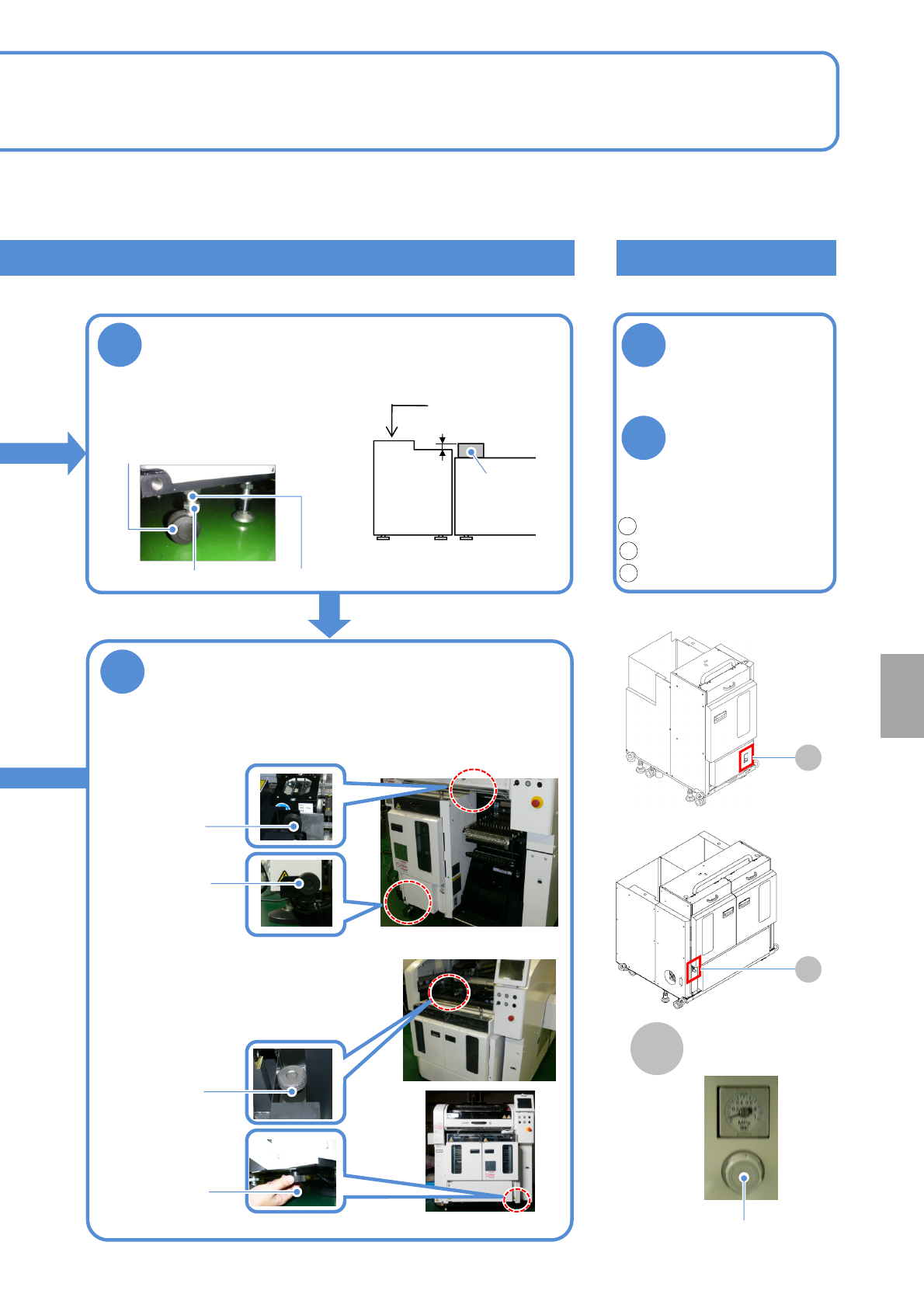
Checking the air pressure
Check the air
pressure
●Air pressure:
0.30 to 0.35 MPa
If it is outside the
specified range,
adjust the air
pressure by
turning the
regulator knob
Unlock.(pull it forward)
Adjust the pressure.(rotate)
Lock.(push it rearward)
4
Adjust the height
1. Loosen the lock nuts.
2. Adjust the height using the
adjustment nuts.
3. Tighten the lock nuts.
19 mm 2 mm
Tray feeder
Mult-
recognition
camera
Level gauge
●Adjust the height/level of
the feeder as shown in the
figure below
Regulator
Lock nut
Adjustment nut
1
2
3
■Single tray feeder
■Twin tray feeder
A
A
A
Air pressure gauge
■For the twin tray feeder
●The bubble should stay
within 1 division (0.1 mm/m)
●Casters: 4 pcs
5
Secure the tray feeder with joint screws
●Secure the tray feeder to the machine with joint screws (A, B).
■For the single tray feeder
Joint screw B
Joint screw A
Joint screw B
Joint screw A
Installation
NPM-W2 EJM7DE-MB-14M-00
14-8-3
How to handle the tray
feeder (option) 2
Maintenance
14-8
Checking the air pressure
Calibration
STEP Item Action Reference
STEP4 Tray
Pickup height
(→P.13-1, 13-19)
Pickup position 1
Pickup position 2
If the tray feeder is removed or installed, calibration must be performed.
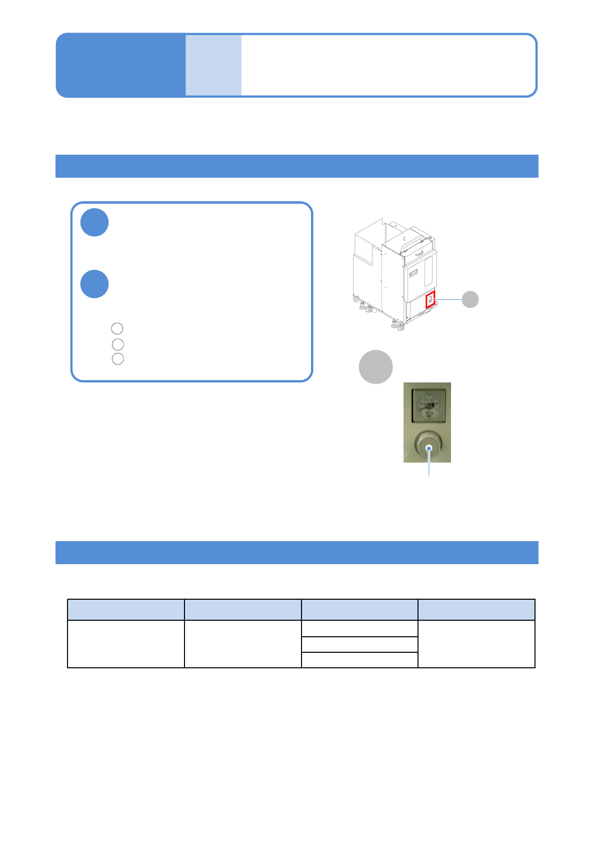
Check the air pressure
●Air pressure:
0.30 to 0.35 MPa
If it is outside the specified
range, adjust the air pressure
by turning the regulator knob
Unlock.(pull it forward)
Adjust the pressure.(rotate)
Lock.(push it rearward)
Regulator
1
2
3
■Tray feeder
A
Air pressure gauge
1
2
A
NPM-W2 EJM7DE-MB-14M-00
14-9-1
2D inspection head 1
(option)
Maintenance
14-9
Overview of peripheral equipment
This section describes the peripheral equipment that can be connected to the machine equipped with the
2D inspection head.
●Attachment/Detachment of 2D inspection head, inspection box, calibration jig, and safety cover is
conducted by our service personnel. Please contact us when necessary.
The following equipment can be connected to a machine with the 2D inspection head.
Peripheral equipment and connecting cables are to be prepared on your own.
Display Being connected to the inspection box, it displays the NG map that
shows which part of PCB is judged as NG.
Keyboard and mouse When it is connected to the inspection box, you can check/exit the NG
map on the display and perform display-related operations.
To connect both the keyboard and the mouse, USB HUB is required,
which should be obtained separately.
Network When the inspection box is connected to PCs running LWS and the
NPM-DGS system via a network, data can be created and modified on
the PCs using the image data of the inspection-target PCB sent from the
inspection box.
Do not connect the inspection box to a network other than the one LWS
is connected to.
Installation