N7201A617E00_0317.pdf - 第523页
NPM-W 2 EJM7DE-MB-14M-00 ■ Mouse ● Applicable OS : Windows XP ● Connection inter face : USB 1.1 / 2.0 ● Connect ing cable : Certified according to the USB standards of the mouse to use 5 m or less in length *The maximum …
NPM-W2 EJM7DE-MB-14M-00
14-9-2
Maintenance
14-9
Specifications of peripheral equipment
Describes the specifications required for the peripheral equipment.
■Display
●Resolution : 1024×768 or higher
●Display color : Approximately 16770000 colors or more
●Image input signal : Analog RGB
●Connecting cable : 5 m or less in length
A 75 coaxial cable is recommended for each of the R, G, and B signal lines.
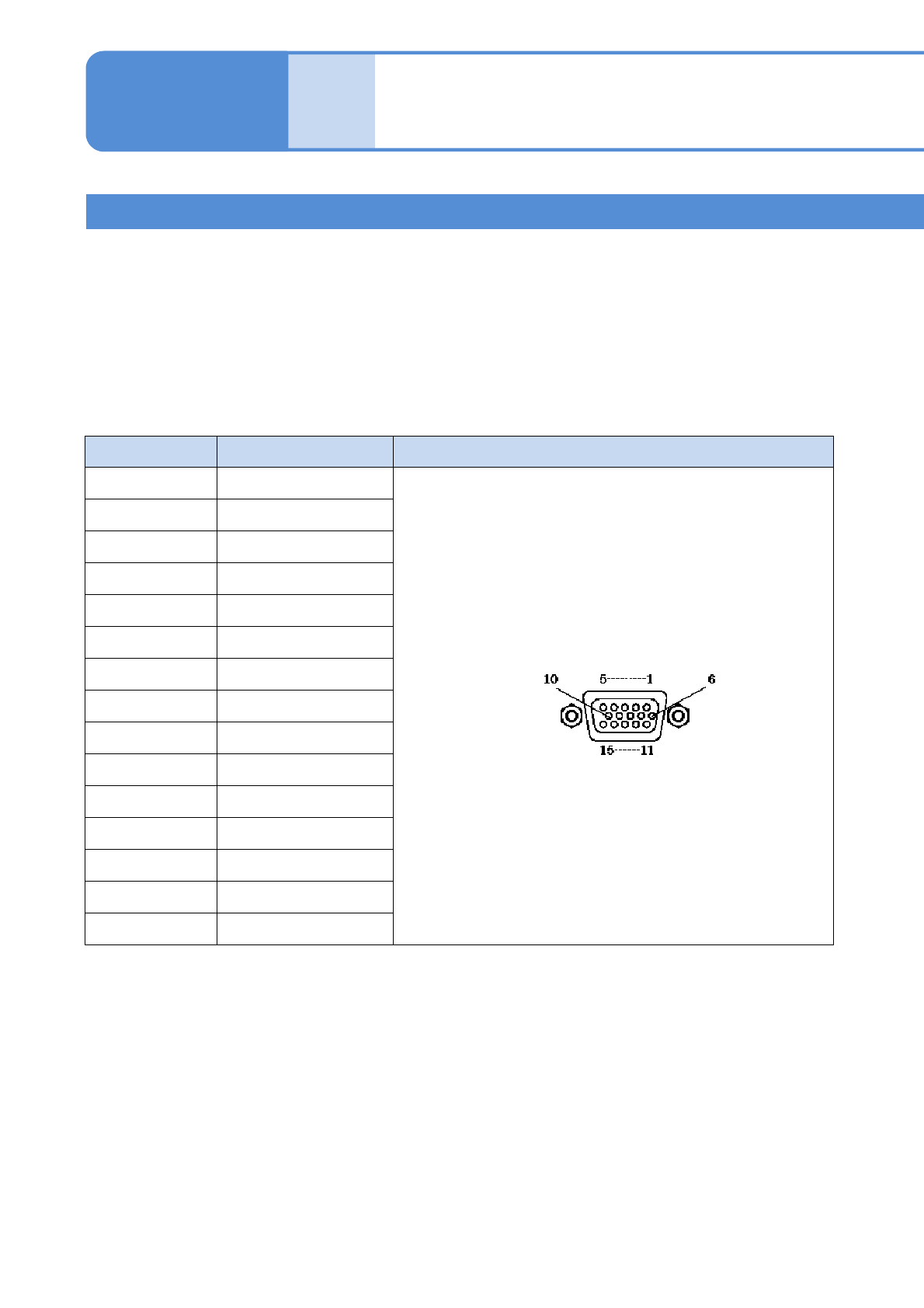
The shape and pin arrangement of the connector ‘MONITOR’ on the inspection box connecting the display are
as follows.
Terminal No. Signal name Pin connection
1GRED
2 GREEN
3GBLUE
4NC
5GND
6GND
7GND
8GND
9 VP50
10 GND
11 NC
12 SDA-10
13 GHSYNC+10
14 GVSYNC+10
15 SCL-10
Connector: Mini D-sub 15 pin (Female)
■Keyboard
●Language : English or Japanese
●Applicable OS : Windows XP
●Connection interface : USB 1.1 / 2.0
●Connecting cable : Certified according to the USB standards of the keyboard to use
5 m or less in length
*The maximum current derived from the USB connector on the inspection box is 500 mA (DC+5V).
2D inspection head 2
(option)

NPM-W2 EJM7DE-MB-14M-00
■Mouse
●Applicable OS : Windows XP
●Connection interface : USB 1.1 / 2.0
●Connecting cable : Certified according to the USB standards of the mouse to use
5 m or less in length
*The maximum current derived from the USB connector on the inspection box is 500 mA (DC+5V).
■Network
●LAN type : IEEE802.3ab(1000BASE-T)
Use connecting cables and network equipment that comply with the above
standards.
14-9-3
Installation
NPM-W2 EJM7DE-MB-14M-00
14-9-4
Maintenance
14-9
Connecting peripheral equipment
Describes how to connect the peripheral equipment.
1
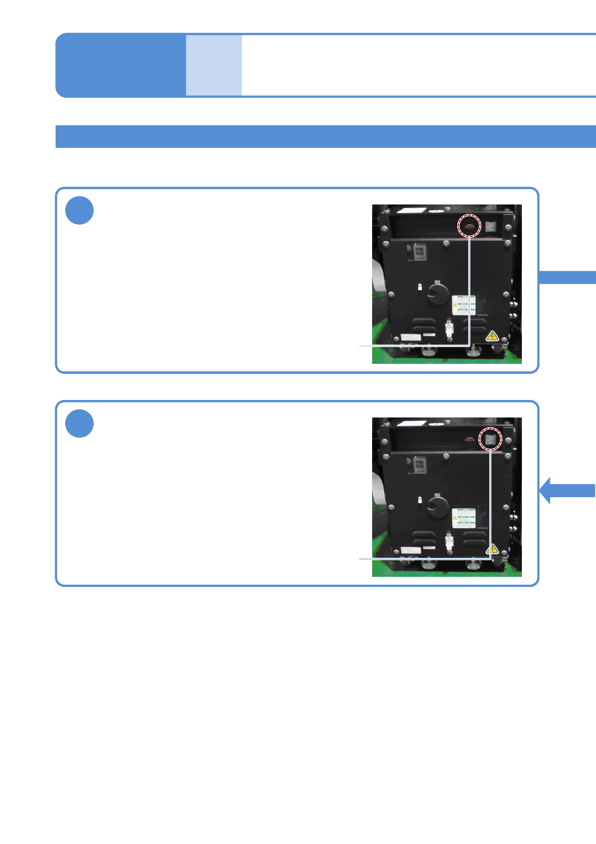
Connect the display
Remove the connector cap of the MONITOR connector on
the inspection box, and connect the monitor cable.
Tighten the two locking screws of the cable connector to
secure it.
MONITOR connector
3
Connect the network
Open the ETHERNET connector cover on the inspection
box, and connect an Ethernet cable to the RJ-45 jack.
Do not connect the inspection box to a network other than
the one LWS is connected to.
ETHERNET connector
2D inspection head 3
(option)