N7201A617E00_0317.pdf - 第525页
NPM-W 2 EJM7DE-MB-14M-00 14-9 -5 2 Connect the keyboard and mouse Turn the USB c onnector cap on the ins pection box to the right by 90 degrees to open the conne ctor hole. USB connection Put your finger into the catch h…
NPM-W2 EJM7DE-MB-14M-00
14-9-4
Maintenance
14-9
Connecting peripheral equipment
Describes how to connect the peripheral equipment.
1
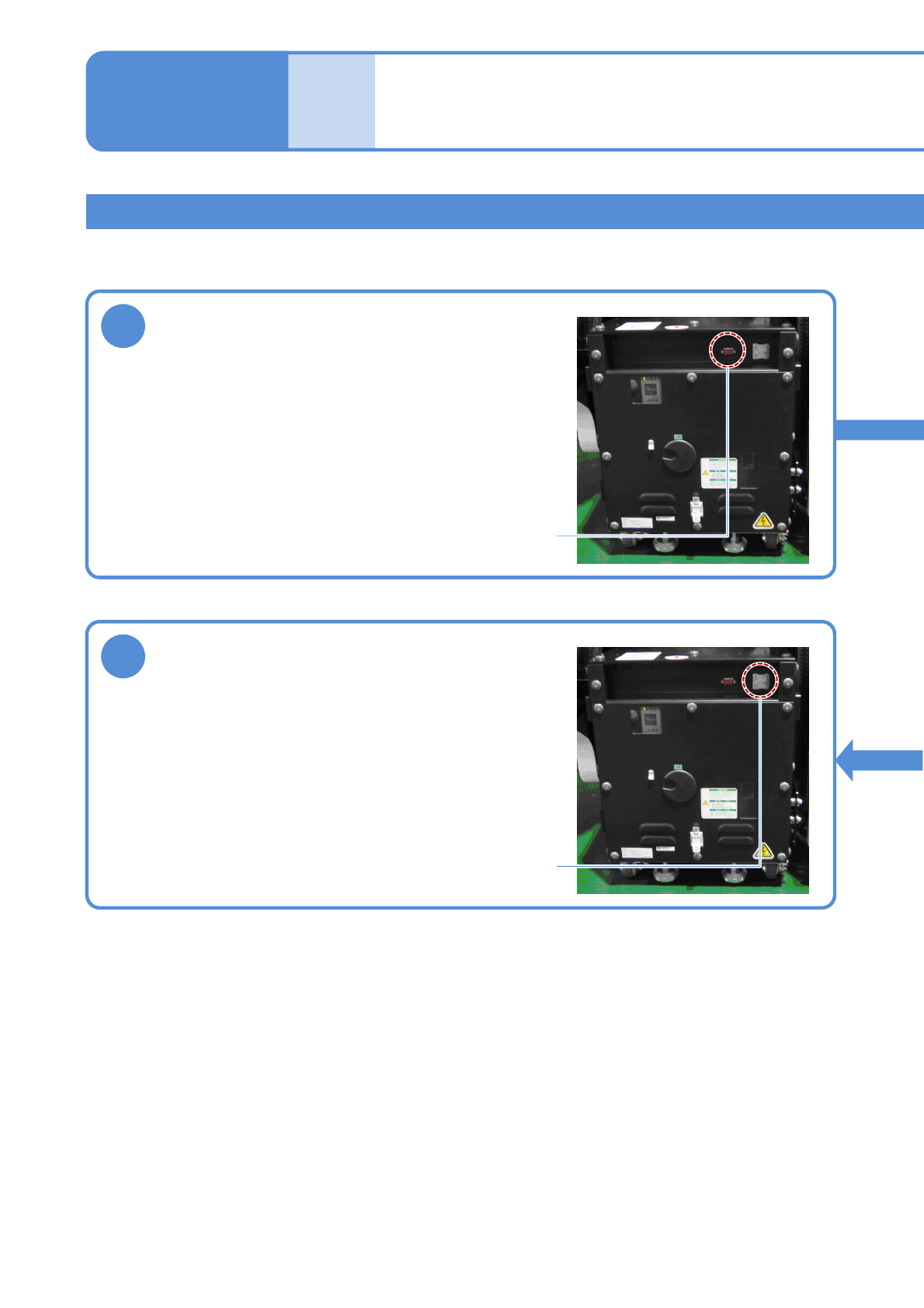
Connect the display
Remove the connector cap of the MONITOR connector on
the inspection box, and connect the monitor cable.
Tighten the two locking screws of the cable connector to
secure it.
MONITOR connector
3
Connect the network
Open the ETHERNET connector cover on the inspection
box, and connect an Ethernet cable to the RJ-45 jack.
Do not connect the inspection box to a network other than
the one LWS is connected to.
ETHERNET connector
2D inspection head 3
(option)
NPM-W2 EJM7DE-MB-14M-00
14-9-5
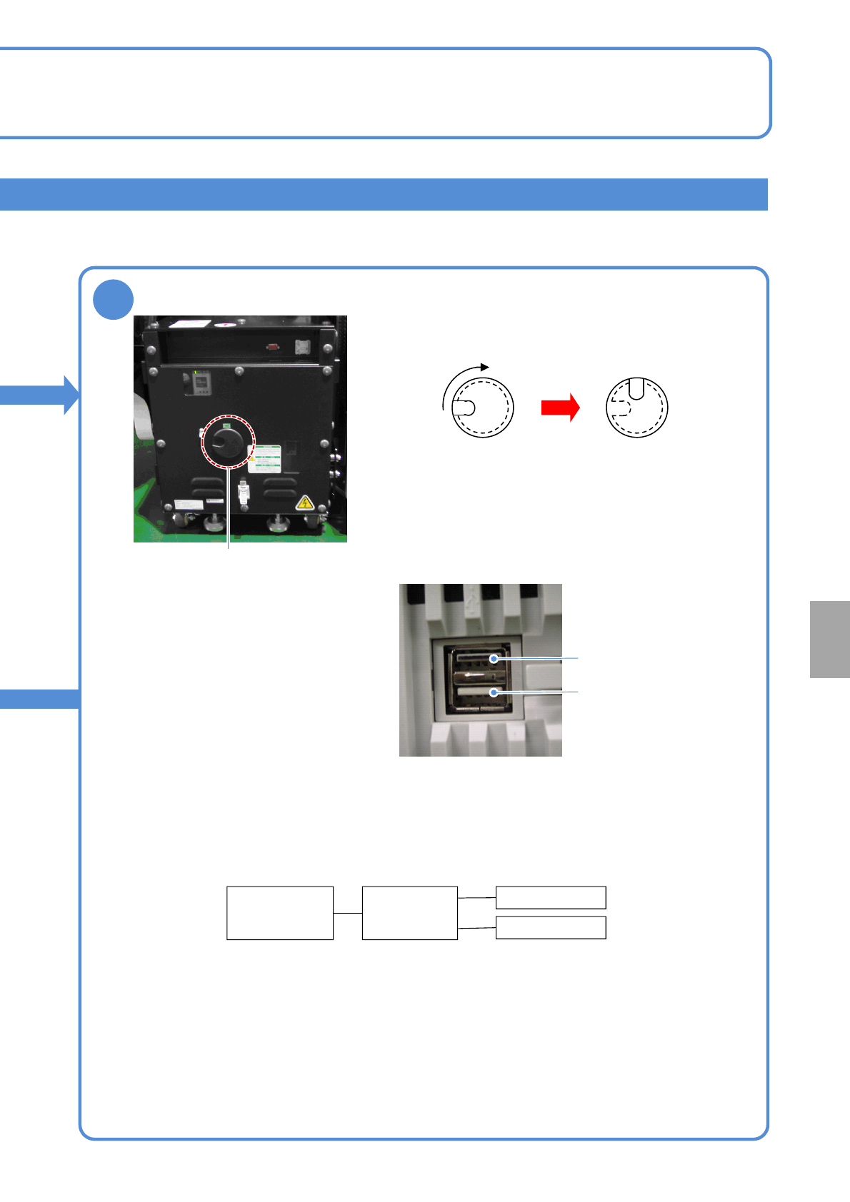
2
Connect the keyboard and mouse
Turn the USB connector cap on the inspection box to the
right by 90 degrees to open the connector hole.
USB connection
Put your finger into the catch hole, and remove the cap.
Connect the USB cable connector to the USB connector of
the inspection box FA computer via the cap-removed
opening. Although there are two USB connectors arranged
one above the other, use the lower connector for connection.
The upper connector painted in black does not work.
After connecting the USB cable, put the cap back in such a
manner that the route of the cable and catch hole align.
*1) Self-powered USB HUB is recommended. In this case, power needs to be supplied to USB HUB
separately.
To use a bus-powered HUB, the total current consumed by the HUB, keyboard, and mouse needs to be
500 mA or lower.
Connection unavailable
Connect the USB cable
To connect both the keyboard and the mouse, USB HUB is required between the inspection box and the
keyboard / the mouse. USB HUB should be obtained separately.
Inspection
box
USB HUB
*1)
Keyboard
Mouse
When connecting both the keyboard and mouse
Installation
NPM-W2 EJM7DE-MB-14M-00
Optional function Description Peripheral equipment
Solder inspection NG
ejection function
Based on the inspection result of PCB ejected from
the NPM-W2, OK or NG signal is output so as to
pass through the PCB if it is OK, and to stop if it is
NG. In addition, PCBs are checked on the conveyor
or removed from the conveyor for repair or re-check,
the function which outputs the request signal as
NPM-W2 ejects the next PCB is required.
Component inspection
NG ejection function
Re-load function This function activates with [Component inspection
NG ejection function]. A repaired NG PCB is re-
loaded and the machine performs re-placement of a
component which could not be placed with the
diagonal head or re-inspection. Moreover, the
removed NG PCB is controlled by a barcode and its
trace is controlled by reading the barcode when the
PCB is re-loaded.
NG map display
function
Although inspection NG location can be checked on
the screen of the machine, it also can be displayed
on the screen of the computer during component
inspection.
14-9-6
2D inspection head 4
(option)
Maintenance
14-9
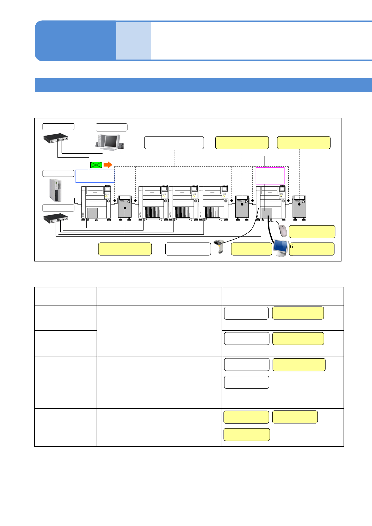
Line configuration
Line configuration including machines equipped with the 2D inspection head and equipment to be used for
them are explained here.
When the following optional functions are used, peripheral equipment required for their functions must be
prepared.
*Peripheral equipment with ‘Customer’ noted must be prepared yourself.
(3) Inspection ejection
conveyor (Customer)
(8) Mouse
(Customer)
(6) Display
(Customer)
(4) Re-load conveyor
(Customer)
(5) Wired scanner
(2) Inspection ejection
conveyor (Customer)
NPM-DGS
(7) Connection cable
(Customer)
LNB
HUB
HUB
(1) Extension conveyor
Solder inspection
(SPI)
Component
inspection
(AOI)
(1) Extension
conveyor
(1) Extension
conveyor
(2) Inspection ejection
conveyor (Customer)
(5) Wired scanner
(4) Re-load conveyor
(Customer)
(3) Inspection ejection
conveyor (Customer)
(1) Extension
conveyor
(7) Connection cable
(Customer)
(6) Display
(Customer)
(8) Mouse
(Customer)