N7201A617E00_0317.pdf - 第68页
NPM-W 2 EJM7DE-SF-01N-0 0 A ppear ance dia g ram/Oper at ing units 1-9-1 -1 1-9-1 Front side Rear side Appearance diagram Com- ponent names Safety cover (Front side) Touchscreen (Front side) Safety cover (Rear side) Touc…
NPM-W2 EJM7DE-SF-01N-00
1-8-2
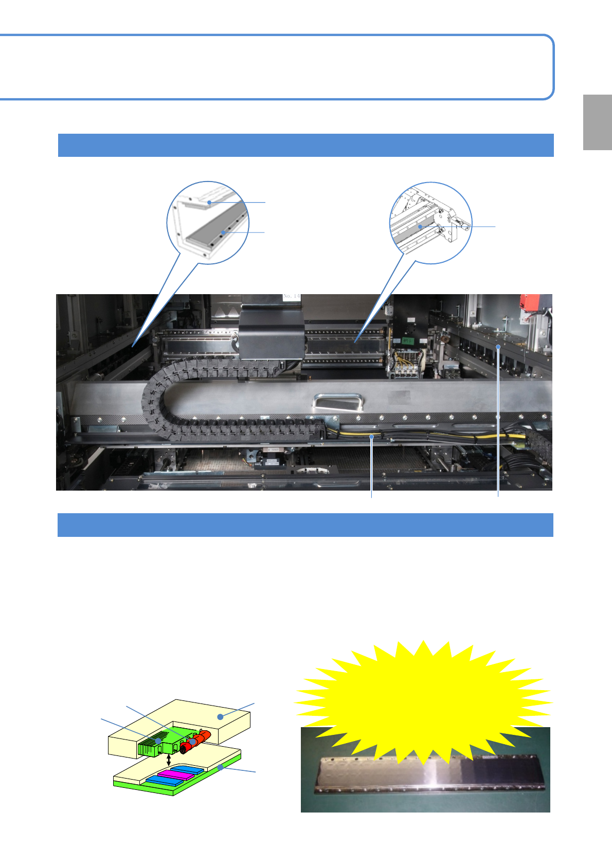
Position of a liner motor
■Structure of the linear motor (reference)
●The structure may differ slightly from one model to
another, but basically it is the same in each model.
Stator
Mover
Iron core
●The attractive force generated by the stator (permanent magnet) is very strong. (it varies depending on the
axis and it is 10 000 at the maximum). Once one stator is stuck to another or a thick steel sheet, they cannot
be detached from each other easily.
●A magnetic body (e.g. tool, jig, or bolt), such as iron, or a device, including a watch, cellular phone, or
magnetic card, should be kept 40 mm away from the linear motor. (It results in serious injury when the stator
attracts the magnetic body and then your finger or hand is caught between them/The strong magnetic force
may damage the watch or the cellular phone and destroy the data on the magnetic card)
●Only the stator has an attractive force. (The mover does not have an attractive force)
Precautions in use
Be careful
of magnetic
force!
(Maximum force
of 10 000 N)
Coil
Confirmation
X-axis liner motor
Y-axis upper stator
(magnet)
Y-axis lower stator
(magnet)
Y-axis liner motor X-axis liner motor
X-axis stator
(magnet)
NPM-W2 EJM7DE-SF-01N-00
Appearance
diagram/Operating units
1-9-1-1
1-9-1
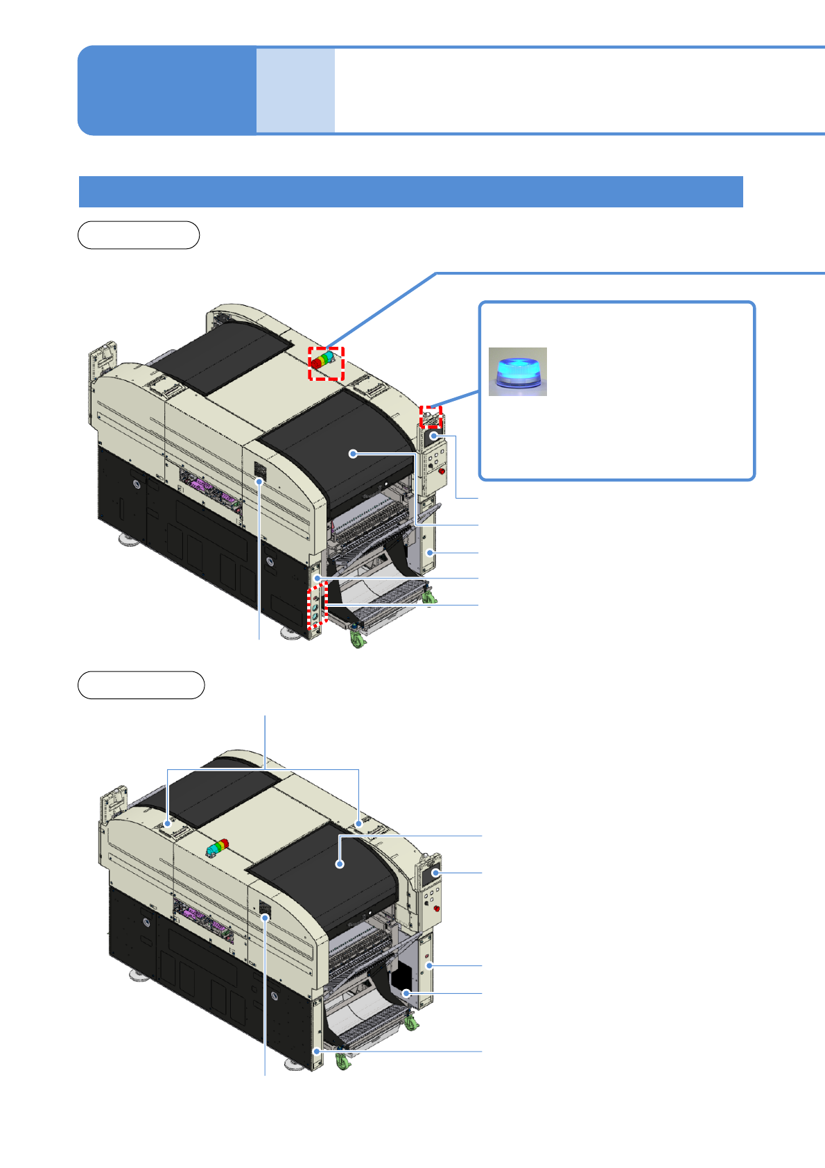
Front side
Rear side
Appearance diagram
Com-
ponent
names
Safety cover (Front side)
Touchscreen (Front side)
Safety cover (Rear side)
Touchscreen (Rear side)
Regulator cover (Rear side)
Component empty lamp
Power supply cover (Rear side)
Various pressure gauges
Regulator cover (Front side)
Cover (Front side)
Cover (Rear side)
Inlet
Outlet
Light OFF: Normal run
Light ON: Components have
run out
Flashing: Shortage of component
Inlet
NPM-W2 EJM7DE-SF-01N-00
1-9-1-2
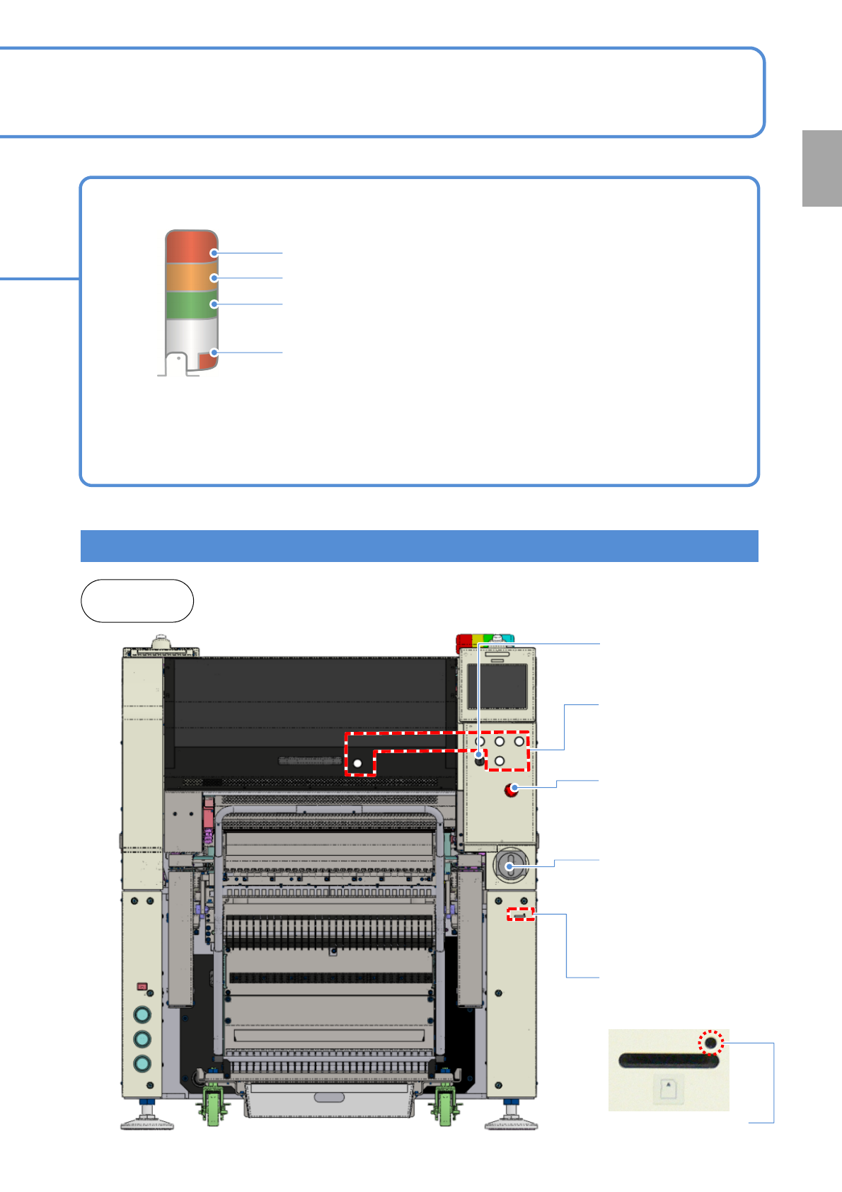
Operating units
Signal tower
Red: Illuminates when you push emergency stop switch or in case
of error stop.
Yellow: Illuminates in case of material shortage.
Green: Illuminates in automatic operation.
Red: Illuminates when you push emergency stop switch or in case
of error stop.
●You can change the above setting. (→ [Operation Edition P.7-1-3)
●Please refer to the [Operating Procedure] (→ P.7-2-4)
●The signal tower is placed sideways when shipped , however the angle can be adjusted.
Front and
rear sides
Confirmation
Emergency stop
switch
Stops operation
immediately
Main power supply
switch (Front side)
Turns ON/OFF the power and
air supply.(When you turn off
the power supply switch, the
air supply is shut off also.)
Various operation
switches
Controls operation start /
stop.
Access lamp
(Green LED)
SD card reader
Reading and writing of
programming data.
Servo switch
Turns ON/OFF the
power of servo units.