SM411 Introduction(Chi Ver1) - 第64页
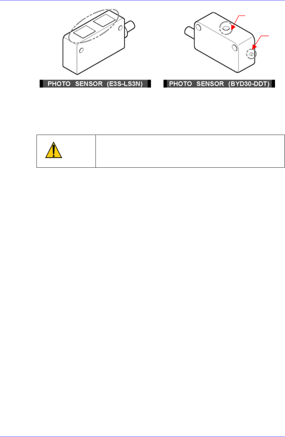
Samsung Component Placer SM41 1 Intr oduction 5-4 图 5-3. 传感器的调整 PHOTO SENSOR (E3S-LS3N) : PCB 感知 传感器 (Front W ork, Rear W ork) PHOTO SENSOR (BYD30-DDT) : PCB 感知传感器 (Entry , Exit) 警 告 当设备准备运行时调整传感器或纠正错误会造成人员受伤。 一定要在设备…
传感器的功能
5-3
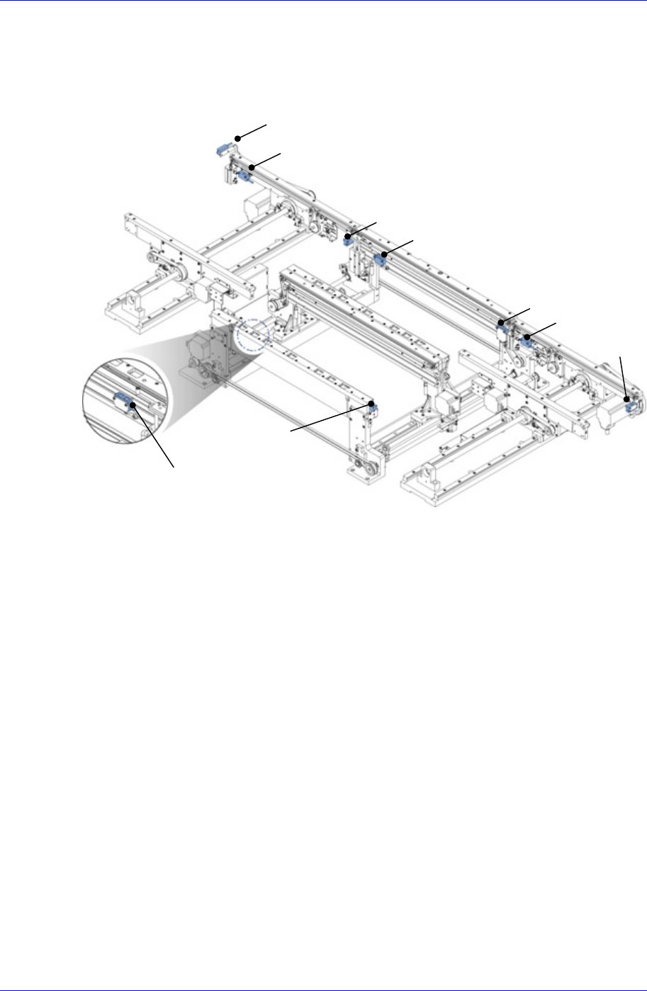
5.3. PCB的感应传感器
传送装置(Conveyor)的PCB输入/输出路径上安装了4个PCB的感应传感器。
图
5-2. PCB
感应传感器的安装位置
各传感器位置及感应内容如下。
Entry Sensor1: 感应从前面工序到本设备的 PCB 的进入。
Entry Sensor2: 检查是否正常完成往 Entry Station 的 PCB 搬运。
Work Sensor1:检查从 Entry Station 到对应 Work Station 的 PCB 搬运。
Work Sensor2:在对应 Work Station 的部件实装位置检查 PCB。
Exit Sensor1: 检查从 Work Station 到 Exit Station 的 PCB 搬运。
Exit Sensor2: 检查 PCB 是否正常完成往 Exit Station 搬运。
BoardOut Sensor: 检查 PCB 是否从本设备中正常搬运到下个工序的设备中。
红色LED在对象被感应时灯亮。
BoardOut Sensor
Work Front Sensor2
Exit Sensor2
Entry Sensor1
Exit Sensor1
Work Front Sensor1
Entry Sensor2
Work Rear Sensor2
Work Rear Sensor1
Samsung Component Placer SM411 Introduction
5-4
图
5-3.
传感器的调整
PHOTO SENSOR (E3S-LS3N) : PCB感知传感器(Front Work, Rear Work)
PHOTO SENSOR (BYD30-DDT) : PCB感知传感器(Entry, Exit)
警 告
当设备准备运行时调整传感器或纠正错误会造成人员受伤。
一定要在设备解除准备运行的停止状态下(Idle模式)调整
传感器或纠正错误。
Red
LED
Sensor
window
传感器的功能
5-5
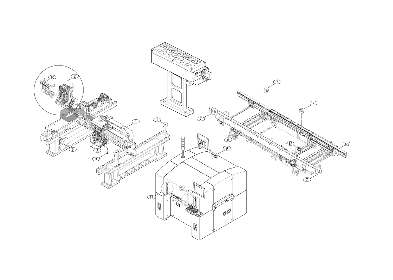
5.4. 设备上传感器的位置
5.4.1. The Sensor Lay-Out(传感器的排列图)
图
5-4.
传感器的
Layout