00195364-0102_Ext_Power_COT_D1_D2_D3_HF - 第24页
2 External power supply unit for component trolleys from the SIPLACE D1/D2/D3/HF series SIPLACE 11/2006 Edition 24 2.5.2 Connecting the component trolley D3 / HF series : Connect the component trolley D3 / HF series to t…
SIPLACE 2 External power supply unit for component trolleys from the SIPLACE D1/D2/D3/HF series
11/2006 Edition
23
2.5 Commissioning
2.5.1 Connecting the component trolley D1/D2
: Connect the component trolley D1/D2 to the power supply unit.
To do this, plug the connector on the power cable for the component trolley to the multi-function
connector on the power supply unit and lock with the clip.
Optional: If a set-up station PC is used, connect the CAN bus cable 03040465-01 (not supplied
as standard) to the CAN bus interface on the back of the power supply unit.
: Attach the pneumatic system coupling provided correctly to the compressed air line.
: Attach the compressed air line to the compressed air connection.
: First switch the power switch off and then plug the EU mains cable 00308240-01 or the US
mains cable 03011615-01 into the combination mains connector.
DANGER
The air outlet opening of the integral fan and the ventilation slots on the side of the unit must not
be covered.
This could cause overheating, which would damage the power supply.
DANGER
Make sure that no one is working on the connected component trolley when you switch on the
power supply. 2
: Switch the power switch on.
On the front of the device there is a green signal lamp. The power supply unit is working correctly
when this lights up. 2
2
: Release the adjusting cap of the pressure reducer by lifting the cap and then turning it until the
manometer reads an output pressure of 2.5 bar (=250 kPa).
2
Turn the cap clockwise to increase the output pressure. 2
2
: After making the setting, press the cap down again to lock it.
2 External power supply unit for component trolleys from the SIPLACE D1/D2/D3/HF series SIPLACE
11/2006 Edition
24
2.5.2 Connecting the component trolley D3 / HF series
: Connect the component trolley D3 / HF series to the power supply unit using the power cable
provided 03050810-01.
: Then lock both the multifunction connector on the power supply unit and the connector on the
component trolley using the locking clip.
Optional: If a set-up station PC is used, connect the CAN bus cable 03040465-01 (not supplied
as standard) to the CAN bus interface on the back of the power supply unit.
: Attach the quick-connect coupling provided correctly to the compressed air line.
: Attach the compressed air line to the compressed air connection.
: First switch the power switch off and then plug the EU mains cable 00308240-01 or the US
mains cable 03011615-01 into the combination mains connector.
DANGER
The air outlet opening of the integral fan and the ventilation slots on the side of the unit must not
be covered.
This could cause overheating, which would damage the power supply. 2
DANGER
Make sure that no one is working on the connected component trolley when you switch on the
power supply. 2
: Switch the power switch on.
On the front of the device there is a green signal lamp. The power supply unit is working correctly
when this lights up. 2
: Release the adjusting cap of the pressure reducer by lifting the cap and then turning it until the
manometer reads an output pressure of 2.5 bar (=250 kPa).
2
Turn the cap clockwise to increase the output pressure. 2
2
: After making the setting, press the cap down again to lock it.
SIPLACE 2 External power supply unit for component trolleys from the SIPLACE D1/D2/D3/HF series
11/2006 Edition
25
2.6 Preventive maintenance
2.6.1 Compressed air filter
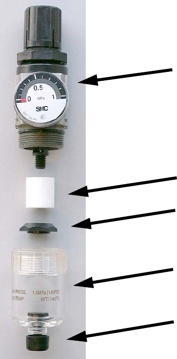
If the flow rate decreases severely, replace the microfilter (see picture below). 2
Release the quick-release coupling and detach it from the compressed air connection. Then un-
screw the condensate tank from the pressure reducer. When you turn down on the separating cap,
you can remove the microfilter. 2
Reverse the above sequence to insert the new microfilter. 2
2
Fig. 6 Compressed air filter unit
2.6.2 Condensate
The transparent condensate tank (see picture above) must be emptied before the condensate
level reaches the separating cap. To do this, turn the manual condensate drain knob to the left
(towards 0 <--). 2
Pressure-reducing valve
Microfilter
Separating cap
Knob for manually draining the condensate
Condensate tank