Mr. JF Sun ALL syringe_IPS.pdf - 第151页
Edition 2.0 NXT/NXT2 R epair Training T ext H12HS(Q) Head FK-9F98-61-0E 14-3 FUJI MACHINE MFG . CO., L TD. 7. Select [W ake] – [A utomatic recognition] – [OK] to tur n ON the servo power . A fter approximately 10 seconds…
Edition 2.0 NXT/NXT2 Repair Training Text
H12HS(Q) Head
FK-9F98-61-0E
14-2
FUJI MACHINE MFG. CO., LTD.
14.2 Preparation on the module
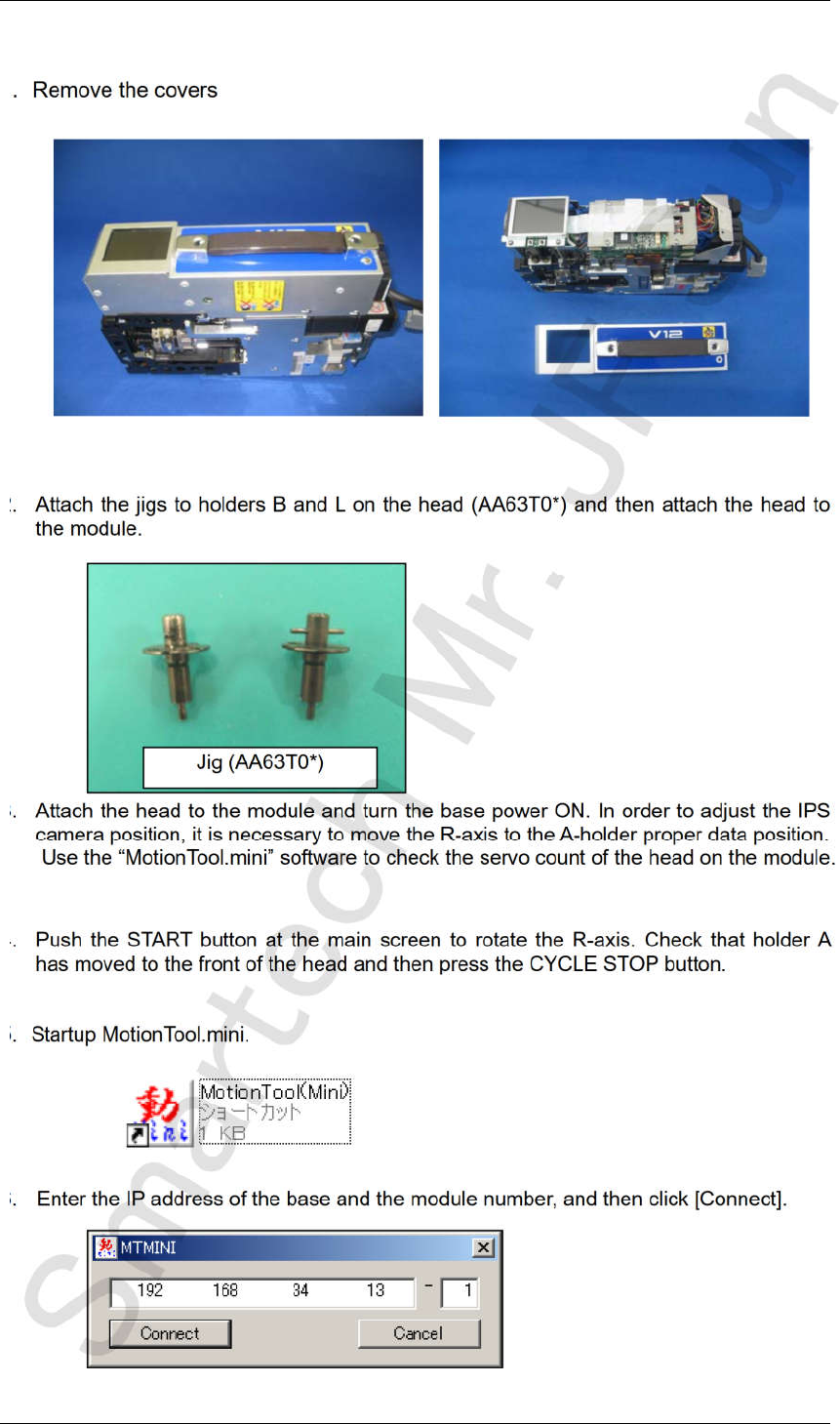
1. Remove the covers
2. Attach the jigs to holders B and L on the head (AA63T0*) and then attach the head to
the module.
3. Attach the head to the module and turn the base power ON. In order to adjust the IPS
camera position, it is necessary to move the R-axis to the A-holder proper data position.
Use the “MotionTool.mini” software to check the servo count of the head on the module.
4. Push the START button at the main screen to rotate the R-axis. Check that holder A
has moved to the front of the head and then press the CYCLE STOP button.
5. Startup MotionTool.mini.
6. Enter the IP address of the base and the module number, and then click [Connect].
Jig (AA63T0*)
CONFIDENTIAL
Edition 2.0 NXT/NXT2 Repair Training Text
H12HS(Q) Head
FK-9F98-61-0E
14-3
FUJI MACHINE MFG. CO., LTD.
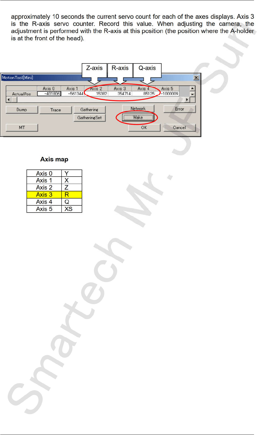
7. Select [Wake] – [Automatic recognition] – [OK] to turn ON the servo power. After
approximately 10 seconds the current servo count for each of the axes displays. Axis 3
is the R-axis servo counter. Record this value. When adjusting the camera, the
adjustment is performed with the R-axis at this position (the position where the A-holder
is at the front of the head).
Axis map
Axis 0
Y
Axis 1
X
Axis 2
Z
Axis 3 R
Axis 4 Q
Axis 5 XS
Z-axis R-axis Q-axis
CONFIDENTIAL
Edition 2.0 NXT/NXT2 Repair Training Text
H12HS(Q) Head
FK-9F98-61-0E
14-4
FUJI MACHINE MFG. CO., LTD.
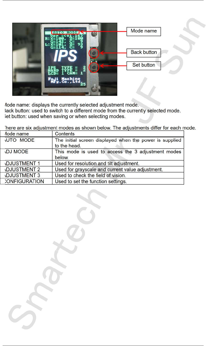
14.3 Component names and explanation of the adjustment modes
Mode name: displays the currently selected adjustment mode.
Back button: used to switch to a different mode from the currently selected mode.
Set button: used when saving or when selecting modes.
There are six adjustment modes as shown below. The adjustments differ for each mode.
Mode name Contents
AUTO MODE The initial screen displayed when the power is supplied
to the head.
ADJ MODE This mode is used to access the 3 adjustment modes
below.
ADJUSTMENT 1 Used for resolution and tilt adjustment.
ADJUSTMENT 2 Used for grayscale and current value adjustment.
ADJUSTMENT 3 Used to check the field of vision.
CONFIGURATION Used to set the function settings.
Back button
Set button
Mode name
CONFIDENTIAL