Mr. JF Sun ALL syringe_IPS.pdf - 第166页
Edition 4.0 H08M(Q) Head Repair T raining T ext FK-9F98-86-0E 5-2 FUJI MACHINE MFG . CO., L TD. 5.2 Prep aration 1. Remove the covers. 2. Attach the jigs (AA9F A0*) to holders B and H on the head, and then attach the hea…
Edition 4.0 H08M(Q) Head Repair Training Text
FK-9F98-86-0E 5-1 FUJI MACHINE MFG. CO., LTD.
Chapter 5 – IPS Adjustment
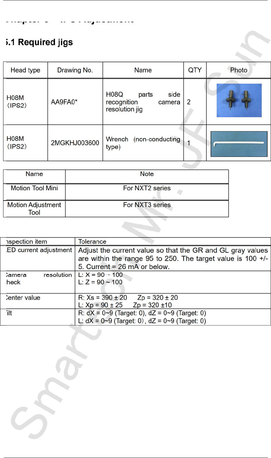
5.1 Required jigs
Head type Drawing No. Name QTY Photo
H08M
IPS2
AA9FA0*
H08Q parts side
recognition camera
resolution jig
2
H08M
IPS2
2MGKHJ003600
Wrench (non-conducting
type)
1
Name Note
Motion Tool Mini For NXT2 series
Motion Adjustment
Tool
For NXT3 series
Inspection item Tolerance
LED current adjustment
Adjust the current value so that the GR and GL gray values
are within the range 95 to 250. The target value is 100 +/-
5. Current = 26 mA or below.
Camera resolution
check
L: X = 90 ~ 100
L: Z = 90 ~ 100
Center value R: Xs = 390 ± 20 Zp = 320 ± 20
L: Xp = 90 ± 25 Zp = 320 ±10
Tilt R: dX = 0~9 (Target: 0), dZ = 0~9 (Target: 0)
L: dX = 0~9 (Target: 0 , dZ = 0~9 (Target: 0)
CONFIDENTIAL
Edition 4.0 H08M(Q) Head Repair Training Text
FK-9F98-86-0E 5-2 FUJI MACHINE MFG. CO., LTD.
5.2 Preparation
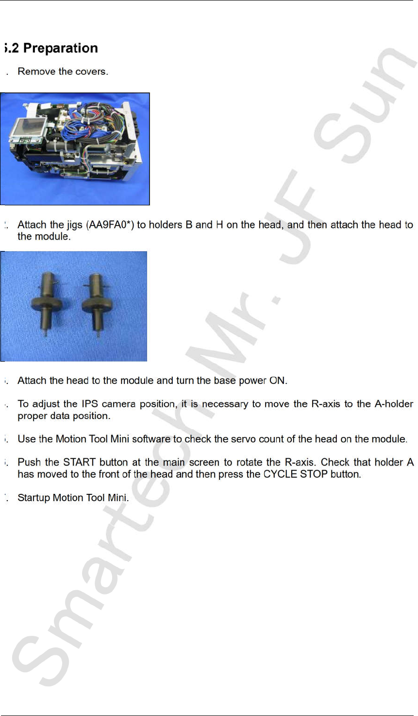
1. Remove the covers.
2. Attach the jigs (AA9FA0*) to holders B and H on the head, and then attach the head to
the module.
3. Attach the head to the module and turn the base power ON.
4. To adjust the IPS camera position, it is necessary to move the R-axis to the A-holder
proper data position.
5. Use the Motion Tool Mini software to check the servo count of the head on the module.
6. Push the START button at the main screen to rotate the R-axis. Check that holder A
has moved to the front of the head and then press the CYCLE STOP button.
7. Startup Motion Tool Mini.
CONFIDENTIAL
Edition 4.0 H08M(Q) Head Repair Training Text
FK-9F98-86-0E 5-3 FUJI MACHINE MFG. CO., LTD.
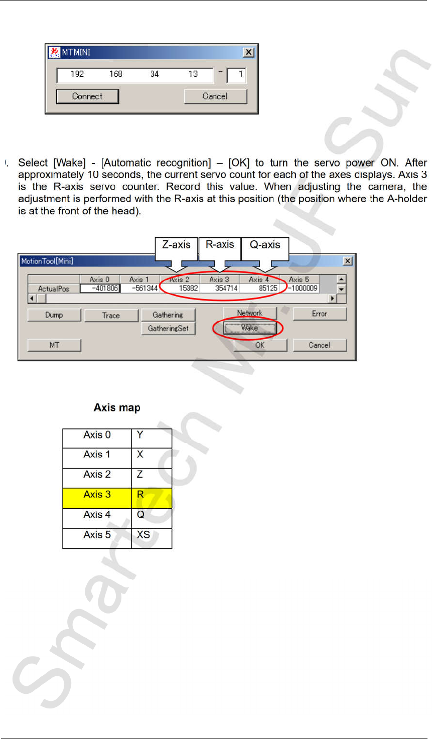
8. Enter the base IP address and the module number, and then click [Connect].
9. Select [Wake] - [Automatic recognition] – [OK] to turn the servo power ON. After
approximately 10 seconds, the current servo count for each of the axes displays. Axis 3
is the R-axis servo counter. Record this value. When adjusting the camera, the
adjustment is performed with the R-axis at this position (the position where the A-holder
is at the front of the head).
Axis map
Axis 0
Y
Axis 1
X
Axis 2
Z
Axis 3 R
Axis 4 Q
Axis 5 XS
Z-axis
R-axis
Q-axis
CONFIDENTIAL