Mr. JF Sun ALL syringe_IPS.pdf - 第173页
Edition 4.0 H08M(Q) Head Repair T raining T ext FK-9F98-86-0E 5-9 FUJI MACHINE MFG . CO., L TD. 9. Af ter loosening the bolts above, adjust the position of the came ra so that the resolution, center and tilt values are a…
Edition 4.0 H08M(Q) Head Repair Training Text
FK-9F98-86-0E 5-8 FUJI MACHINE MFG. CO., LTD.
4. Use Motion Tool Mini to check that the A holder is at the front of the head.
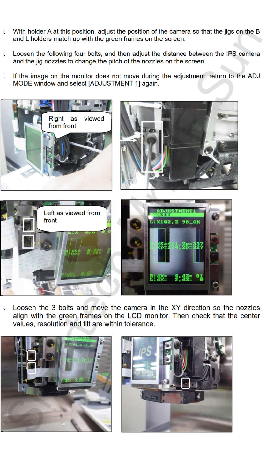
5. With holder A at this position, adjust the position of the camera so that the jigs on the B
and L holders match up with the green frames on the screen.
6. Loosen the following four bolts, and then adjust the distance between the IPS camera
and the jig nozzles to change the pitch of the nozzles on the screen.
7. If the image on the monitor does not move during the adjustment, return to the ADJ
MODE window and select [ADJUSTMENT 1] again.
8.
Loosen the 3 bolts and move the camera in the XY direction so the nozzles
align with the green frames on the LCD monitor. Then check that the center
values, resolution and tilt are within tolerance.
Left as viewed from
front
Right as viewed
from front
CONFIDENTIAL
Edition 4.0 H08M(Q) Head Repair Training Text
FK-9F98-86-0E 5-9 FUJI MACHINE MFG. CO., LTD.
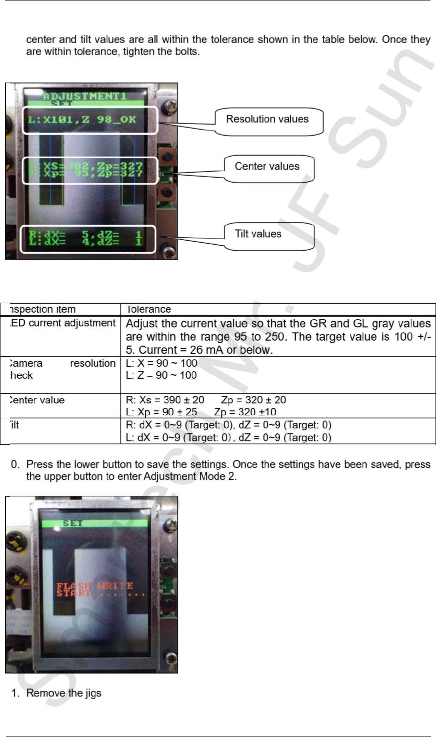
9. After loosening the bolts above, adjust the position of the camera so that the resolution,
center and tilt values are all within the tolerance shown in the table below. Once they
are within tolerance, tighten the bolts.
10. Press the lower button to save the settings. Once the settings have been saved, press
the upper button to enter Adjustment Mode 2.
11. Remove the jigs
Inspection item Tolerance
LED current adjustment
Adjust the current value so that the GR and GL gray values
are within the range 95 to 250. The target value is 100 +/-
5. Current = 26 mA or below.
Camera resolution
check
L: X = 90 ~ 100
L: Z = 90 ~ 100
Center value R: Xs = 390 ± 20 Zp = 320 ± 20
L: Xp = 90 ± 25 Zp = 320 ±10
Tilt R: dX = 0~9 (Target: 0), dZ = 0~9 (Target: 0)
L: dX = 0~9 (Target: 0 , dZ = 0~9 (Target: 0)
Resolution values
Center values
Tilt values
CONFIDENTIAL
Edition 4.0 H08M(Q) Head Repair Training Text
FK-9F98-86-0E 5-10 FUJI MACHINE MFG. CO., LTD.
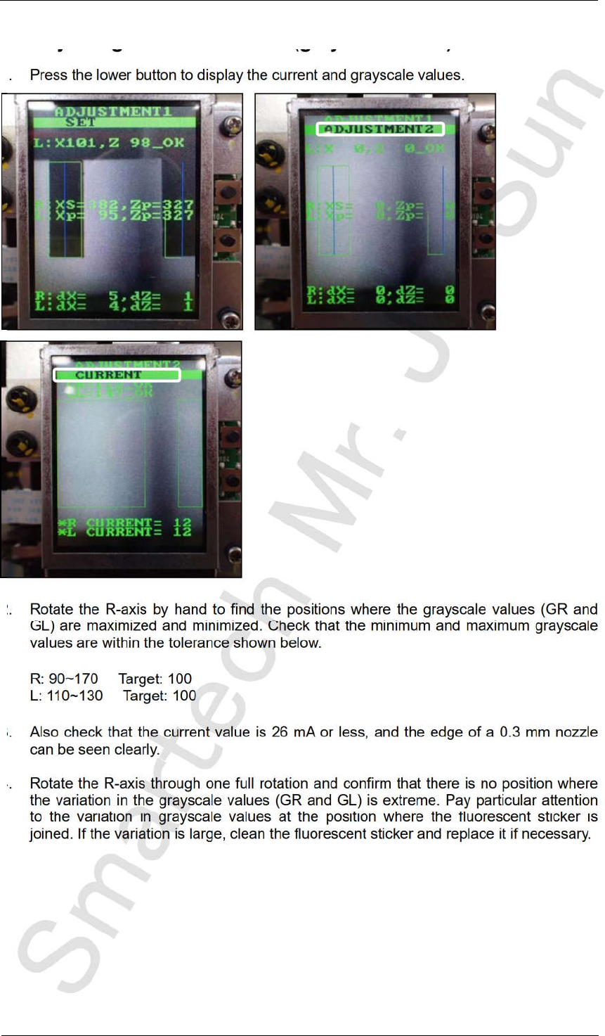
5.6 Adjusting the current value (grayscale value)
1. Press the lower button to display the current and grayscale values.
2. Rotate the R-axis by hand to find the positions where the grayscale values (GR and
GL) are maximized and minimized. Check that the minimum and maximum grayscale
values are within the tolerance shown below.
R: 90~170 Target: 100
L: 110~130 Target: 100
3. Also check that the current value is 26 mA or less, and the edge of a 0.3 mm nozzle
can be seen clearly.
4. Rotate the R-axis through one full rotation and confirm that there is no position where
the variation in the grayscale values (GR and GL) is extreme. Pay particular attention
to the variation in grayscale values at the position where the fluorescent sticker is
joined. If the variation is large, clean the fluorescent sticker and replace it if necessary.
CONFIDENTIAL