YS12调整.pdf - 第10页
Service Engineer Service I nformati on SI080 4004 E-000 = YS12 , YG12: Procedure for adjustmen t after installa tion of the mach ine 10/60 4.3.2. How to check the parallelism and the initial po sition of th e movable con…
Service Engineer
Service Information
SI0804004E-000 = YS12, YG12: Procedure for adjustment after installation of the machine
9/60
4.3. How to check the paralellism and the width of the conveyor
After making sure that the X-Axis and the reference conveyor are parallel to each other, check the
parallelism between the reference conveyor and the movable conveyor, and the reference of the
conveyor width.
4.3.1. Check the parallelism of the reference conveyor
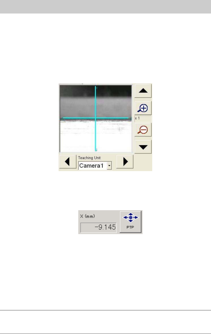
1. Obtain the coordinate of the Y-axis at the edge face of the reference conveyor near the main
stopper by performing teaching with the fiducial camera.
Fill in the coordinate of the Y-axis on the check sheet.
Figure 6
2. Move the X-axis 400mm to the plus (+) direction.
Click on the [PTP] button and move the X-axis 400mm to the plus (+) direction from the
current position by entering the value in the input field.
(If the PCB transport direction is from left to right, move the axis 400mm to the minus (-)
direction.)
Figure 7
3. Obtain the coordinate of the Y-Axis again after moving the X-axis.
Obtain the coordinate of the Y-Axis again after moving the X-axis by performing teaching for
the same Y-axis coordinate obtained in Procedure 1.
Fill in the coordinate of the Y-axis on the check sheet.
4. Check the difference of the Y-axis coordinates.
Calculate the difference between the Y-axis coordinate obtained in Procedure 1 and the
Y-axis coordinate obtained after moving the X-axis.
Fill in the value on the check sheet.
<Specification>: The difference in the Y direction is less than 0.05mm
Note:
If the result does not fall within specification, please check if the reference conveyor and the
movable conveyor are parallel to each other and the conveyor is not interfere with the cover of the
machine.

Service Engineer
Service Information
SI0804004E-000 = YS12, YG12: Procedure for adjustment after installation of the machine
10/60
4.3.2. How to check the parallelism and the initial position of the movable conveyor
[Required tools]
- Glass board for the mounting adjustment (240X170mm)
Used for checking the conveyor width.
- A 0.5mm thick scale or a 0.5mm thickness gauge
Used for checking the clearance between the conveyor edge and the board edge
1. Change the conveyor width to 170mm.
Click on the [Conveyor Width] button on the “Conveyor” tab in the “Unit” screen, then change
the conveyor width to 170.0mm.
2. Check the clearance between the conveyor edge and the board edge.
Press the glass conveyor against the reference conveyor and set it. Then insert the 0.5mm
thick scale between the board edge and the movable conveyor edge to check if there is a
proper clearance between them.
<Positions to be checked>
- At the entrance side of the conveyor
- At the center of the conveyor (mounting position)
- At the exit side of the conveyor
If there is no problem with the clearance, fill in the relevant column of the check sheet.
[If the clearance between the board edge and the conveyor edge is not properly kept]
If the clearance between the board edge and the movable conveyor edge is not 0.5mm,
please perform adjustment.
(1)
When the clearance is even but not appropriate.
Please perform “Initial position” adjustment of the W-axis on the “Soft Limit” screen
in the CalibSm.
(2)
When the clearance is getting smaller/bigger as it goes to the entrance/exit side of the
conveyor. (The clearance on the left side and on the right side is different.)
Adjust the initial position of the ball screws of the W-axis on the right side and on the
left side so that they move in synchronization with each other.
(3)
When the clearance is partly different.
Make sure that the W-axis is not damaged, and then adjust the position of the
conveyor guide plate.
4.3.3. Check if the board can be transferred smoothly between the main machine and the
upstream/ downstream machines
After making sure that the conveyor of the machine has no abnormality, adjust the conveyor
width of the upstream machine and the downstream machine to be equal, and check if a
board can be transferred smoothly between the machines.
If a board can be transferred smoothly, fill in the relevant column of the check sheet.
Service Engineer
Service Information
SI0804004E-000 = YS12, YG12: Procedure for adjustment after installation of the machine
11/60
4.4.How to adjust the PCB height
“PCB height” is the reference height for the head to mount components, and is automatically
measured according to the changes in the vacuum pressure of the nozzle when it contacts the
board surface. The “Vacuum Level“ needs to be adjusted before measuring the PCB height.
Measure the four points on the top surface of the aluminum frame of the Glass QFP, and save the
height of the lowest point as the “PCB height”.
<Tools used for adjustment>
KHN-M7720-A0X NOZZLE 302A ASSY.
Nozzle for chip
components
(Standard set)
KHY-M7730-A0X NOZZLE 313A ASSY.
Nozzle for chip
components
(Narrow pitch set)
Use either of the
nozzle
KM0-M8810-40X GLASS PCB ASSY.4 ACP glass board
KM0-M8810-10X GLASS PCB ASSY.1 AMF glass board
Use either of the board
Table 6
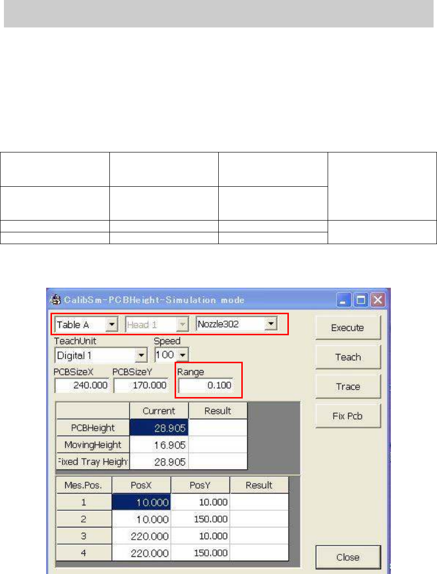
1. Click on the [PCB height] button on the main screen of the CalibSm.
Figure 8
2. Check the nozzle to be used.
Select “Nozzle 302A” or “Nozzle 313” as the PCB height is measured by the difference of the
vacuum pressure of the nozzle.
3. Check the value in the “Range” field.
The four points on the aluminum frame of the glass board are measured and the difference
between the maximum and minimum value is checked automatically. Please make sure that
the value in the “Range” field (standard value) is “0.100”.