YS12调整.pdf - 第14页
Service Engineer Service I nformati on SI080 4004 E-000 = YS12 , YG12: Procedure for adjustmen t after installa tion of the mach ine 14/60 4.5. How to adjust t he “brightness” of each camera 4.5.1. How to adjust the “b r…
Service Engineer
Service Information
SI0804004E-000 = YS12, YG12: Procedure for adjustment after installation of the machine
13/60
Figure 12
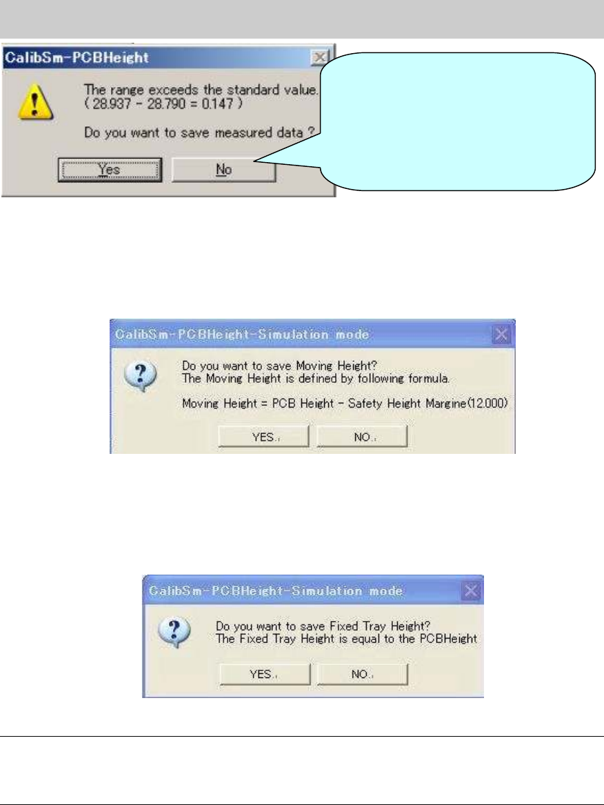
7. Check the value in the “Moving Height” field.
After saving the data of the “PCB Height”, the message appears asking you to save the
“Moving Height”. As the value is calculated automatically, please save the data without change
except for when the special setting is set.
Figure 13
8. Check the value in the “Fixed Tray Height” field.
After saving the data of the “Moving Height”, the message appears asking you to save the
“Fixed Tray Height”. As the value is calculated automatically, please save the data without
change except for when the special setting is set.
Figure 14
Note:
If the 302A nozzle, 313A nozzle and 309A nozzle cannot be prepared, please click on the
[Measuring Height] button on the CalibSm main menu and select “Manual” item to measure the
height manually.
If the difference between the
maximum value and the minimum
value of the PCB height exceeds the
specified value, the message is
displayed on the dialog box. Please
check if the board is clamped properly
and perform adjustment again.
Service Engineer
Service Information
SI0804004E-000 = YS12, YG12: Procedure for adjustment after installation of the machine
14/60
4.5. How to adjust the “brightness” of each camera
4.5.1. How to adjust the “brightness” of the fiducial camera
When the machine is equipped with two fiducial cameras (option), please perform adjustment for
both cameras. The “Black level” adjustment does not need to be performed.
(The “Black level” adjustment needs to be performed only when the camera is replaced.)
<Required tools>
Part No. Part Name Size Feature
KM1-M8806-0** LIGHT ADJUSTER
35mm
square
Dark and light gray + white
KM1-M8806-1** LIGHT ADJUSTER 1
35mm
square
Dark and light gray + white,
with a Φ3 hole
KGT-M8806-0** LIGHT ADJUSTER S
17mm
square
Light gray and white
KHW-M8806-*** LIGHT ADJ.*(1,S, 3,4) ASSY
35mm
square
Dark and light gray + white,
with one chamfered corner
Table 7
[How to secure the tool for “brightness” adjustment]
1. Raise the pushup plate.
Click on the [Push Up] button on the “Conveyor” tab on the “Unit” screen in order to raise the
pushup plate.
Thickness of the board: Input 4.0mm in the “Thickness” field.
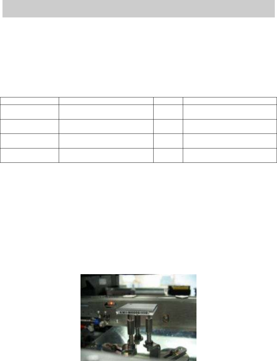
2. Set the pushup pins.
Set three pushup pins so that the tool for brightness adjustment can be placed on them.
3. Place the tool for brightness adjustment on the pushup pins with its gray side facing upward.
If the tool is not parallel, please check if the height of the pushup pins is even.
Figure 15
4. Perform teaching for the gray part of the tool.
Move the head so that the light gray part of the tool fills the screen of the fiducial camera.
*If the scan camera is under the fiducial camera, move it to the left.
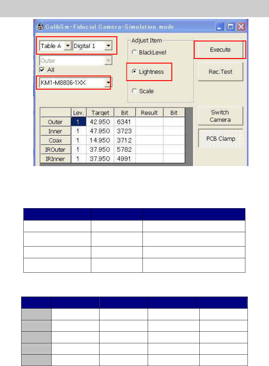
5. Click on the [Fiducial Camera] button on the main screen of CalibSm.
Select “Lightness” from the “Adjust Item”.
Service Engineer
Service Information
SI0804004E-000 = YS12, YG12: Procedure for adjustment after installation of the machine
15/60
Figure 16
6. Select the tool for brightness adjustment.
Select the part number of the tool to be used for the adjustment.
Part No. Size Feature
KM1-M8806-0** 35mm square Dark and light gray + white
KM1-M8806-1** 35mm square
Dark and light gray + white,
with a Φ3 hole
KGT-M8806-0** 17mm square Light gray and white
KHW-M8806-*** 35mm square
Dark and light gray + white,
with one chamfered corner
Table 8
* The target value varies depends on the tools to be used.
Tool KM1-M8806-0XX
KM1-M8806-1XX
KGT-M8806-0XX
KHW-M8806-XXX
Outer 35 35 35 35
Inner 40 40 40 44
Coax 7 7 7 8
IR Outer
35 30 30 31
IR Outer
35 30 30 33
Table 9
* The value that the black level value is added to the set target value is displayed as “Target”
value.
6
7
5