YS12调整.pdf - 第16页
Service Engineer Service I nformati on SI080 4004 E-000 = YS12 , YG12: Procedure for adjustmen t after installa tion of the mach ine 16/60 7. Click on the [Execute] button. If you cli ck on the [Execute] button, the adju…
Service Engineer
Service Information
SI0804004E-000 = YS12, YG12: Procedure for adjustment after installation of the machine
15/60
Figure 16
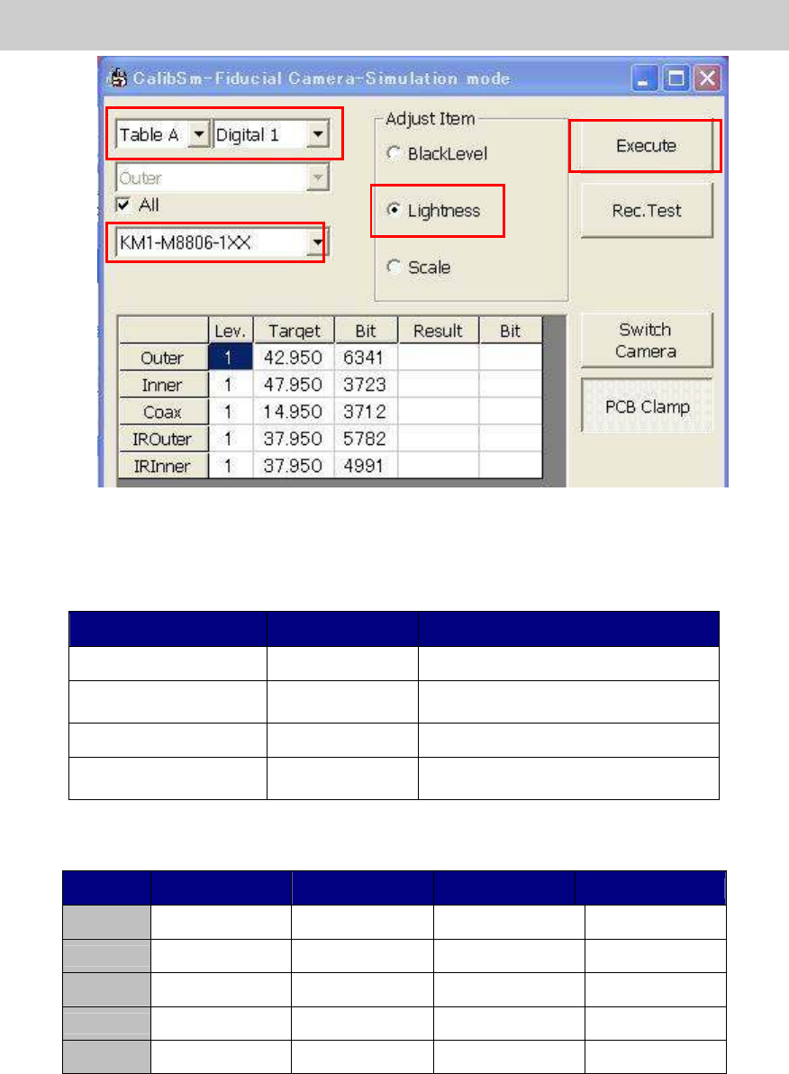
6. Select the tool for brightness adjustment.
Select the part number of the tool to be used for the adjustment.
Part No. Size Feature
KM1-M8806-0** 35mm square Dark and light gray + white
KM1-M8806-1** 35mm square
Dark and light gray + white,
with a Φ3 hole
KGT-M8806-0** 17mm square Light gray and white
KHW-M8806-*** 35mm square
Dark and light gray + white,
with one chamfered corner
Table 8
* The target value varies depends on the tools to be used.
Tool KM1-M8806-0XX
KM1-M8806-1XX
KGT-M8806-0XX
KHW-M8806-XXX
Outer 35 35 35 35
Inner 40 40 40 44
Coax 7 7 7 8
IR Outer
35 30 30 31
IR Outer
35 30 30 33
Table 9
* The value that the black level value is added to the set target value is displayed as “Target”
value.
6
7
5
Service Engineer
Service Information
SI0804004E-000 = YS12, YG12: Procedure for adjustment after installation of the machine
16/60
7. Click on the [Execute] button.
If you click on the [Execute] button, the adjustment of the brightness is automatically
performed.
Figure 17
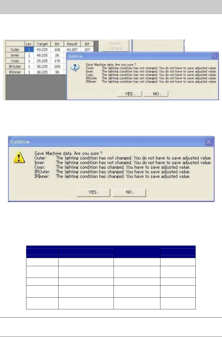
Check if the values in the “Target” and “Bit” fields fall within the specification, and save the data.
[The dialog box indicating that the data needs to be saved]
Figure 18
8. Click on the [Rec.Test] button.
Click on the [Rec.Test] button to perform recognition test and check if the measured values
fall within the tolerance.
If the values fall within the tolerance, please fill in the value on the check sheet.
Target value
Tolerance of the
measured value
Bit
BitBit
Bit value
Outer 35+ Black level value Target value+-2 0 -16128
Inner
40(44)+
Black level value
Target value+-2 0 -16128
Coax 7(8)+ Black level value
Target value+-2 0 -16128
IR Outer
30(31)+
Black level value
Target value+-2 0 -16128
IR Outer
30(33,35)+
Black level value
Target value+-2 0 -16128
Table 10
Note:
If the Bit value does not fall within the specification, please check if the lens of the camera is clean,
if the lighting condition is good or if the connector is connected properly.
Service Engineer
Service Information
SI0804004E-000 = YS12, YG12: Procedure for adjustment after installation of the machine
17/60
Note:
As the maximum value of the Bit value is the warning value for the upper limit, the adjustment can
be performed even when the value exceeds the Bit value.
If the Bit value exceeds 16128 (the seven eighth of the maximum value), it may attribute to the
deterioration of the lighting device. It is recommended to replace the lighting.
(The maximum value of the Bit value: 19400)
As the target value varies depends on the tools used for brightness adjustment, please follow the
specification of the machine.
* If the machine is not equipped with the sub fiducial camera (Option), this is the end of the
brightness adjustment.
9. Switch the fiducial camera. (Option: If the machine is equipped with two fiducial cameras.)
After completing the adjustment of the reference camera (the one on the right), perform
adjustment of the sub fiducial camera (the one on the left).
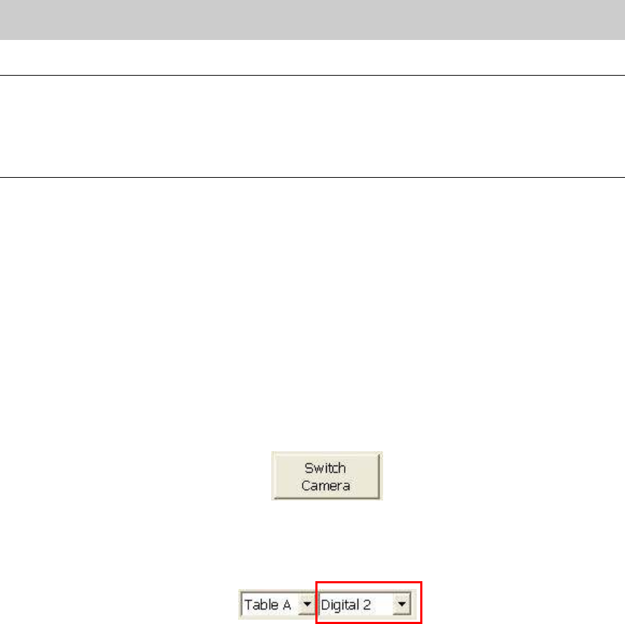
1) Click on the [Switch Camera] button on the “Fiducial Camera” screen to move the sub
camera to above the adjustment tool that is being caught by the reference fiducial
camera.
Figure 19
2) After the sub fiducial camera is moved, the camera number item on the “Fiducial camera”
screen changes from “Digital 1” to “Digital 2” automatically.
Figure 20
3) Check the number of the camera, and perform brightness adjustment.
Check if the values in the “Target” and “Bit” fields fall within the specification, and save
the data.
If the values fall within the specification, please fill in the values on the check sheet.