YS12调整.pdf - 第21页
Service Engineer Service I nformati on SI080 4004 E-000 = YS12 , YG12: Procedure for adjustmen t after installa tion of the mach ine 21/60 4.5.3. How to adjust the “b rightness” of t he multi camera (Optio nal) Though th…
Service Engineer
Service Information
SI0804004E-000 = YS12, YG12: Procedure for adjustment after installation of the machine
20/60
6. Remove the tool for brightness adjustment
When the adjustment is completed, press the [Emergency stop] button and remove the tool.
And then click on the [Vacuum ON/OFF] button to disable the nozzle to pick up the tool.
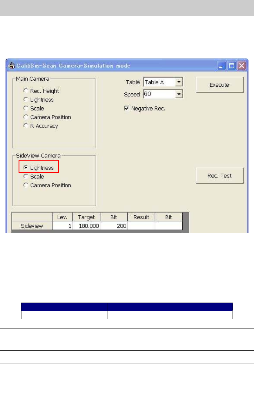
7. Select “Lightness” from the “Side View Camera” item.
Figure 24
8. Start adjustment.
Click on the [Execute] button without setting the tool to start adjustment.
(Adjustment for side view camera does not require any tools.)
Check if the values in the “Target” and “Bit” column fall within the specification, and save the
data.
If the values fall within the specification, please fill in the relevant column of the check sheet.
Color of the tool Tolerance of the measured value
Bit value
Side view
Not used 180+-5 32-448
Table 13
Note:
If the Bit value does not fall within the specification, please check if the lens of the camera is clean,
if the lighting condition is good, or if the connector is connected properly.
Note:
As the maximum value of the Bit value is the warning value for the upper limit, the adjustment can
be performed even when the value exceeds the specification.
If the Bit value exceeds 448 (the seven eighth of the maximum value), it may attribute to the
deterioration of the lighting device. It is recommended to replace the lighting.
(The maximum value of the Bit value: 512)
Service Engineer
Service Information
SI0804004E-000 = YS12, YG12: Procedure for adjustment after installation of the machine
21/60
4.5.3. How to adjust the “brightness” of the multi camera (Optional)
Though the design of the lighting device of the multi camera has been changed, the method of
adjustment is the same as that of the YG series machines.
<Required tools>
Part No. Part Name
KM1-M8806-0XX
LIGHT ADJUSTER
35mm
square
Dark and light gray + white
KM1-M8806-1XX
LIGHT ADJUSTER 1
35mm
square
Dark and light gray + white,
with a Φ3 hole
KGT-M8806-0XX
LIGHT ADJUSTER S
17mm
square
Light gray and white
KHW-M8806-XXX
LIGHT ADJ.*(1,S, 3,4) ASSY
35mm
square
Dark and light gray + white,
with one chamfered corner
Table 14
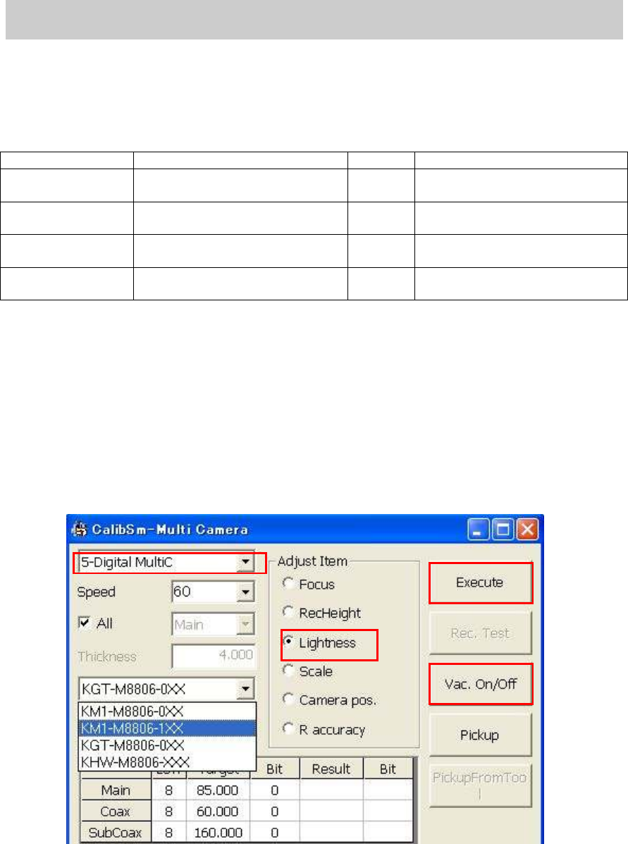
1. Select “Lightness” from the “Adjust Item”.
Click on the [Multi Camera] button on the main menu of CalibSm.
Select “Lightness” from the “Adjust Item”.
2. Select the camera to be adjusted.
If the machine is equipped with one multi camera: “5-digital Multi”
If the machine is equipped with two multi cameras:
<Front>: “5 Digital Multi”
<Rear>: “6-Digital Multi”
Figure 25
3. Select the tool to be used.
Select the tool to be used for brightness adjustment.
The 304 (315) nozzle needs to be used for vacuuming the tool for brightness adjustment.
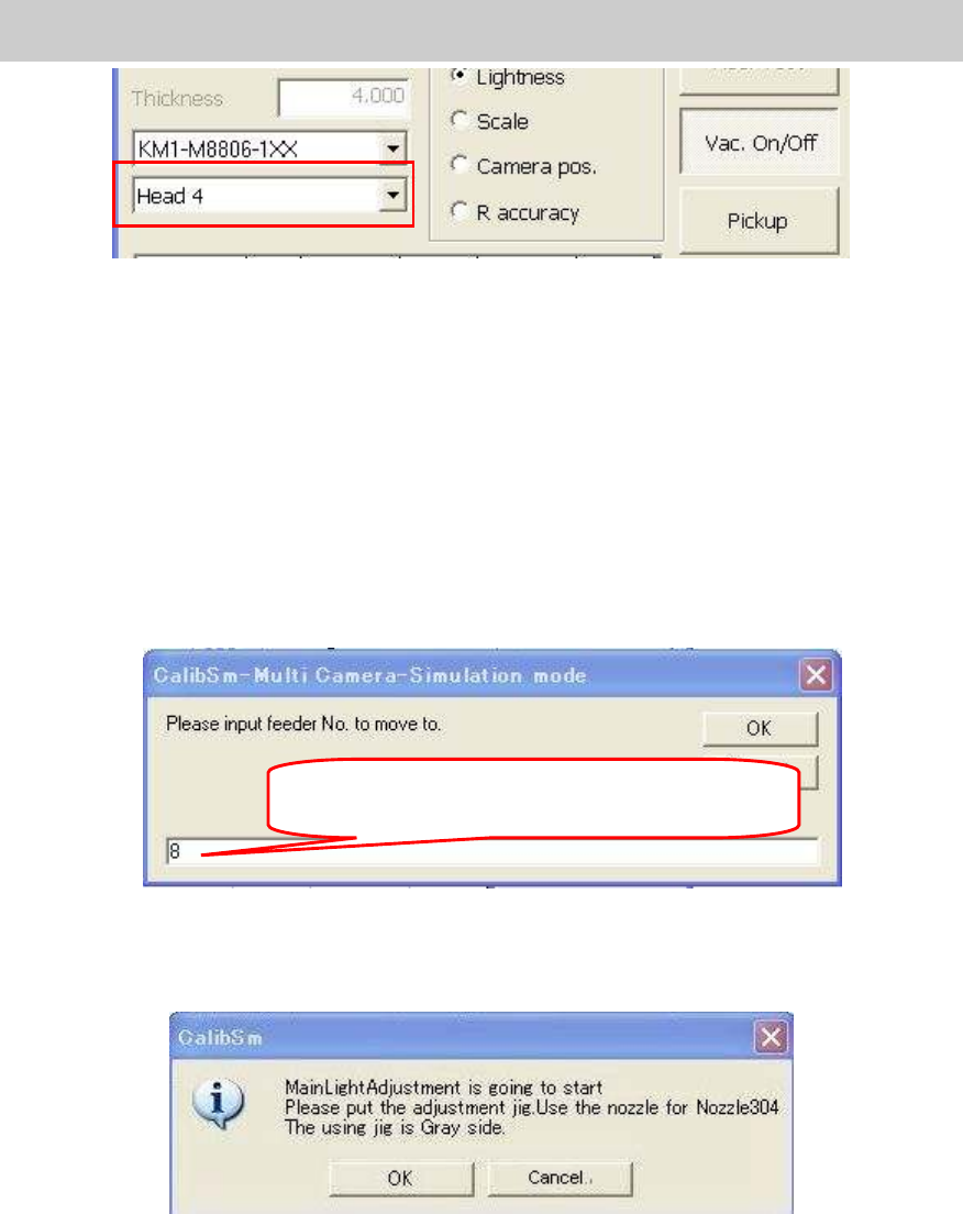
4. Select the head to be used.
When the 303 (314) nozzle is used, the “Head 4” or the “Head 8” is to be selected.
When the machine is not equipped with the 304A (315A), mount the nozzle to the specified
head by hand.
2.
1.
6.
5.
Service Engineer
Service Information
SI0804004E-000 = YS12, YG12: Procedure for adjustment after installation of the machine
22/60
Figure 26
5. Pick up the tool for brightness adjustment.
Use the [Vac.ON/OFF] button.
If you click on the [Vac. ON/OFF] button, the head becomes able to pick up the tool for
brightness adjustment. Press the [Emergency Stop] button and make the nozzle vacuum
the tool with the light gray side facing down.
Use the [Pickup] button.
Click on the [Pickup] button and input the feeder number.
If you click on the [OK] button, the head moves to the pickup position and start
vacuuming Change the nozzle to the 304A (315A) nozzle and make the nozzle vacuum
the tool with the light gray side facing down.
Figure 27
6. Start adjustment.
Click on the [Execute]: button to display the following dialog box.
Figure 28
Check if the tool is set properly and click on the [OK] button to start adjustment.
7. Save the adjustment data.
When the adjustment is completed, the dialog box appears asking you to save the data.
Check if the values in the “Target” and “Bit” fields fall within the specification, and save the
data.
If the values fall within the specification, please fill in the values on the check sheet.
Input the number of the feeder that the head to be
adjusted is able to vacuum.