YS12调整.pdf - 第30页
Service Engineer Service I nformati on SI080 4004 E-000 = YS12 , YG12: Procedure for adjustmen t after installa tion of the mach ine 30/60 5.1.1. Required tools Glass board u sed for adjustment Part No. P…

Service Engineer
Service Information
SI0804004E-000 = YS12, YG12: Procedure for adjustment after installation of the machine
29/60
5. How to check the mounting accuracy (with ACP
1
)
5.1. Preparation for the ACP adjustment
Scan camera is used as a reference camera when performing adjustment of the mounting
accuracy of the YS12 and YG12 models.
Mounting accuracy adjustment is performed by ACP using the ceramic chip.
The nozzle 301A (312A) and the 1005 chip component are normally used for performing the
adjustment.
If the machine is equipped with multi cameras (option), after performing the ACP adjustment with
multi camera using the 1005 chip adjustment, perform FAMF adjustment by mounting the Glass
QFP 68 pin with the 304A (315A) nozzle.
Please make sure to perform the following adjustments (work) before performing the ACP
adjustment (mounting accuracy adjustment) when installing or relocating a machine.
System data back up
Make a backup copy of the system data before performing adjustment after installation of the machine,
or maintenance.
Adjustment of the Y-axis dual drive offset
Correct the deviation between the Y1-axis motor and the Y2-axis motor caused by the relocation of the
machine. The adjustment does not need to be performed when the machine is not relocated or the
motor is not replaced.
Adjustment of the “Orthogonalization level”
Correct the deviation in orthogonality of the axes after relocating a machine.
The adjustment does not need to be performed when the machine is not relocated or the Coord Macs
adjustment is performed.
Adjustment of the “Brightness” (Illumination intensity of lighting) for each camera
Basically the adjustment needs to be performed when the installation environment of the machine is
changed. However if the adjustment is performed during maintenance, it affects the customer’s existing
production data. Please make sure to gain the customer’s approval before performing the adjustment.
Adjustment of the “Fiducial Camera relative position” (Option)
Correct the deviation of the relative position between the reference camera and the sub camera caused
by the relocation of the machine.
[Reference]
Digital camera numbers
Camera No. Type Mounting point
Maximum angle
of view
XY (mm)
Maximum
angle of view
Z (mm)
Mounting
angle
Digital camera 1 Moving camera B
Right side of the head
5 0 90 degrees
Digital camera 2 Moving camera B
Left side of the head
5 0 270 degrees
Digital camera 3 Scan, Main 8 7 0 degree
Digital camera 4 Scan Side view
Integrated
4 2 90 degrees
Digital camera 5 Digital Multi C
* Front /
One multi camera
24 7 0 degree
Digital camera 6 Digital Multi C Rear 24 7 180 degree
Table 19
* When the machine is equipped with two multi cameras:
- Front “Digital 5 / - Rear: Digital 6
When the machine is equipped with only one camera:
Wherever the camera is mounted (Front or Rear), the camera is “Digital 5”.
1
ACP(Accuracy Calibration Program) is an adjustment function for the mounting accuracy used in Calib Sm, which is in
the [Utilities] for YAMAHA surface mounter; YG and YS series.
Service Engineer
Service Information
SI0804004E-000 = YS12, YG12: Procedure for adjustment after installation of the machine
30/60
5.1.1. Required tools
Glass board used for adjustment
Part No. Part Name Board data
Double
-faced tape
ACP
Glass board
KM0-M8810-400
GLASS PCB
ASSY.4
ACP_1005_10HEAD_FL.ygx 20mm width
AMF
Glass board
KM0-M8810-100
GLASS PCB
ASSY.1
ACP_1005_10HEAD__OLD.ygx
35mm width
Component used for adjustment
Part No. Part Name
1005 Ceramic chip component
(Reel component)
KGA-M880C-10* REEL CERAMIC 1005
Table 20
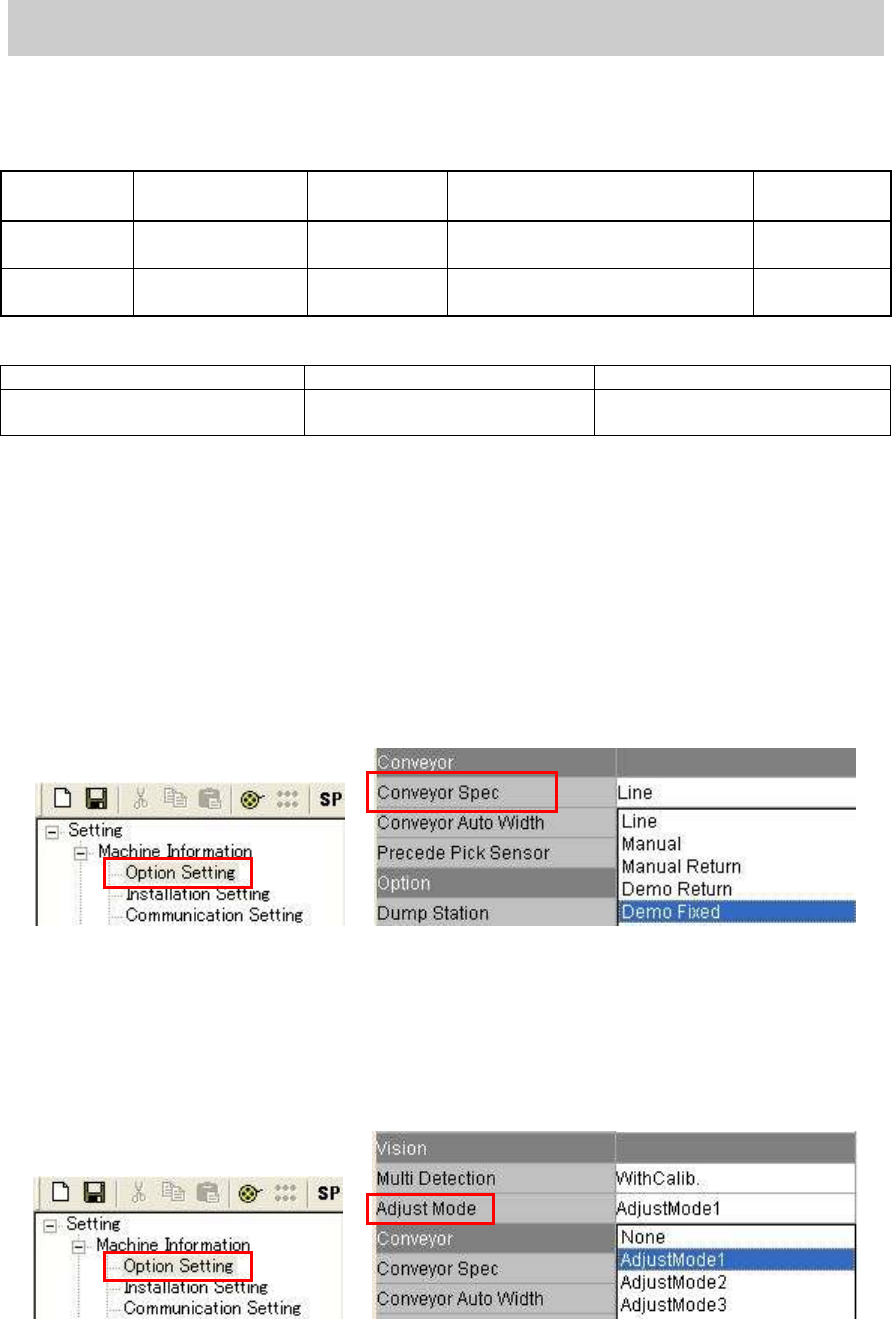
5.1.2. Check and change the option setting
“Conveyor Spec”
When selecting “Demo Fixed":
Set the board on the conveyor and clamp the board manually by clicking on the [Board Clamp]
button on the “Unit “ screen for mounting.
How to change the setting:
Select “Demo Fixed” from the dropdown list of the “Conveyor Spec” item on the “Option
setting “ screen in the “Machine information”.
Figure 39
“Adjust Mode”
When selecting “Adjust Mode 1”:
Performing mounting with the head that caused error when performing retry of mounting.
How to change the setting:
Select “AdjustMode1” from the dropdown list of the “Adjust Mode” item.
Figure 40
Service Engineer
Service Information
SI0804004E-000 = YS12, YG12: Procedure for adjustment after installation of the machine
31/60
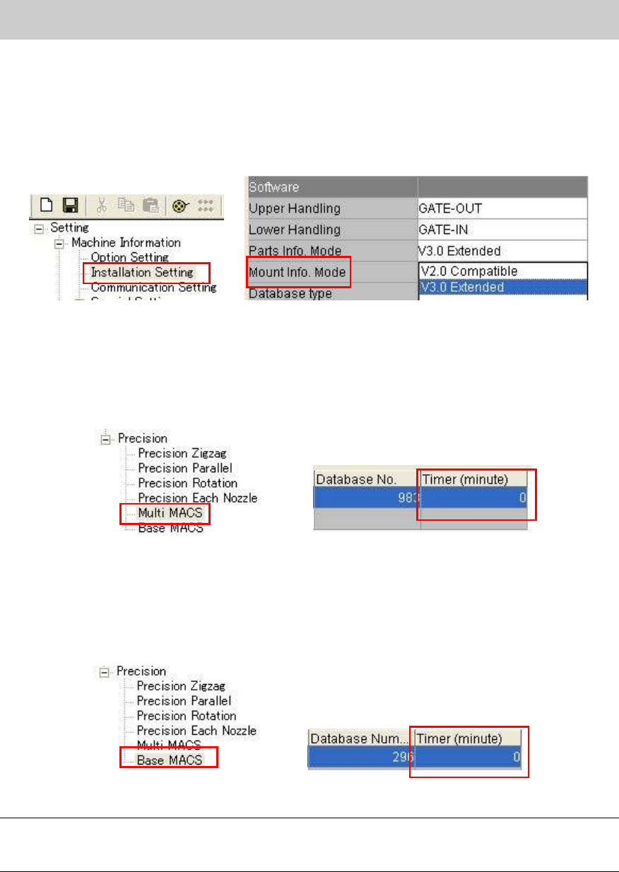
“Mount Info. Mode”
* This mode needs to be set when the machine is equipped with the multi camera.
How to change the setting:
Select “V3.0 Extended” from the dropdown list of the “Parts Info. Mode” in the “Machine
setting”.
Figure 41
“Multi MACS”
As accuracy of repeatability is checked during APC adjustment, the interval time to recognize the
multi MACS needs to be set to 0 in order to recognized Multi MACS each time.
Check if the “Timer (minute)” is set to “0” on the “Multi MACS” screen in the “Precision”.
Figure 42
“Base MACS”
In order to prevent the variation in accuracy from occurring depends on the time for mounting, set
the interval time to “0” so that Multi MACS is recognized each time.
Check if the “Timer (minute)” is set to “0” on the “Base MACS” screen in the “Precision”.
Figure 43
Note:
Please read the board data again in order to reflect the changes when changing the machine
setting.