YS12调整.pdf - 第35页
Service Engineer Service I nformati on SI080 4004 E-000 = YS12 , YG12: Procedure for adjustmen t after installa tion of the mach ine 35/60 [Items to be adju sted] - Fiducial camera pos ition (XY) - Digital 3_Head 1 – 10 …
Service Engineer
Service Information
SI0804004E-000 = YS12, YG12: Procedure for adjustment after installation of the machine
34/60
5.2. The workflow of the ACP adjustment
There are two methods for mounting and measuring of the ACP adjustment.
1. Click on the [All] button in the ACP utility to perform mounting and the measurement
consecutively.
2. Click on the [Auto Run] button to perform mounting, and then click on the [Measure] button to
perform measurement.
The following describes how to perform mounting using the [All] function.
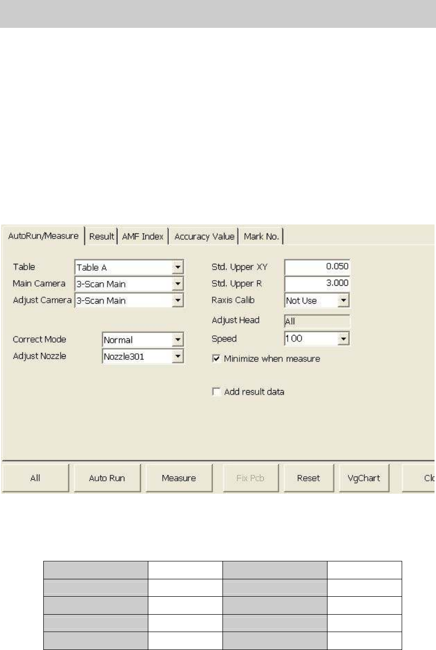
5.2.1. Start up and setting of the ACP utility
1. Click on the [ACP] button on the CalibSm main menu to display the “ACP” screen.
2. How to perform setting on the “AutoRun/Measure” tab.
The main camera of the YS12 is the scan camera (3-Digital Scan Main).
Please check all the settings referring to Table 22.
Table A Table Std. Upper XY 0.050
Main Camera Digital 3 Std. Upper R 3.000
Adjust Camera Digital 3 Raxis Calib Not Use
Correct Mode Normal
Adjust Nozzle Nozzle 301
Table 22
Service Engineer
Service Information
SI0804004E-000 = YS12, YG12: Procedure for adjustment after installation of the machine
35/60
[Items to be adjusted]
- Fiducial camera position (XY)
- Digital 3_Head 1 –10 Precision Zigzag parameter (X, Y): Main nozzle
- Digital 3_Head 2 –10 Precision Parallel parameter (X, Y): Main nozzle
5.2.2. Mounting and measurement performed by ACP
When completing the initial setup and the setting, please perform ACP adjustment.
Though the adjustment is normally performed by [All] function, if the mounting is interrupted and
restarts, please click on the [All] button again or click on the [Auto Run] button.
When the measurement is interrupted and perform only measurement, please click on the
[Measure] button.
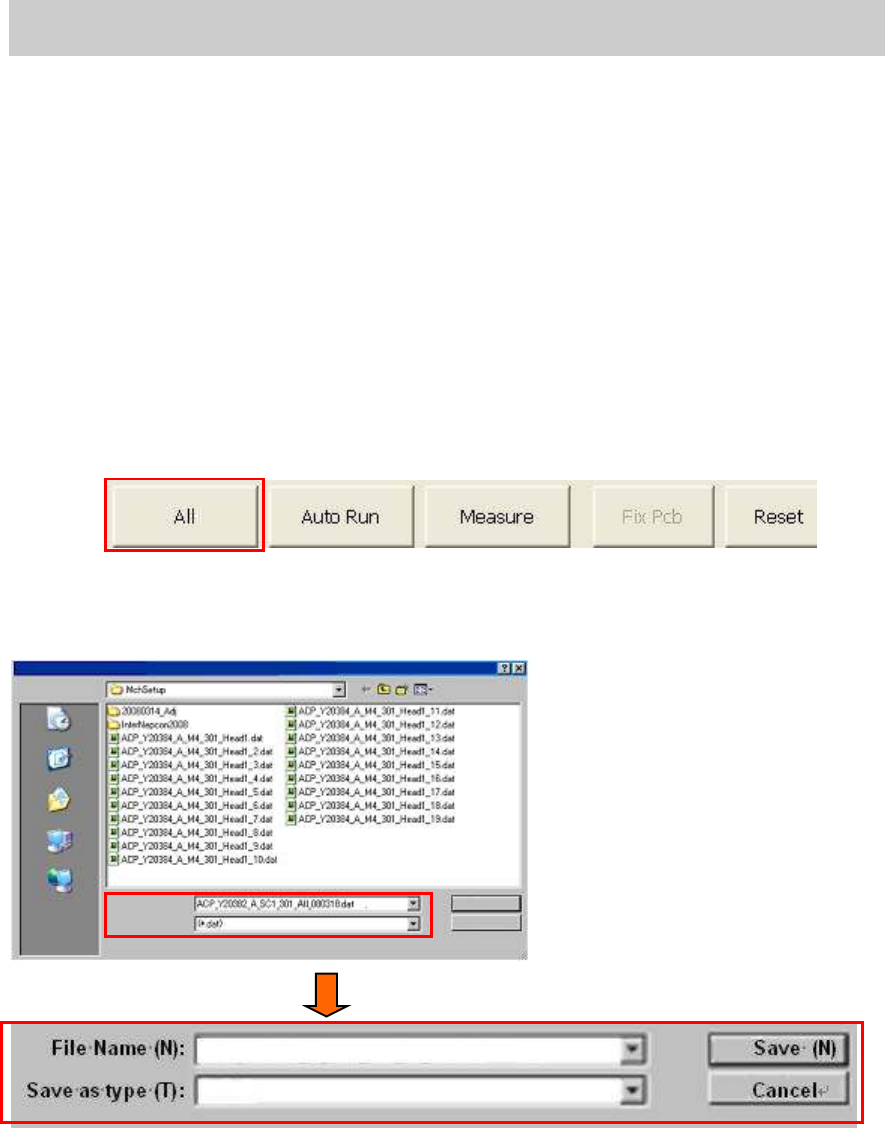
1. Click on the [All] button on the “AutoRun/Measure” tab.
After checking the setting of the ACP adjustment and initial setup of the glass board, click on
the [All] button.
Figure 48
2. Save the measured result and input the file name
Click on the [All] button to display the screen to input the file name of the measured data.
Figure 49
[The name of the file for saving the adjustment data]
The default file name indicates the adjustment method and the item to be adjusted, so you just
need to add the date of the adjustment before the extension (.dat) and save the data.
Save
in:
Recently used file
Desktop
My Document
My Computer
My Network
File Name (N):
Save as type (T):
Save (N)
Cancel
ACP_Y20382_a_SC1_301_All_080318.dat
(*.dat)
Service Engineer
Service Information
SI0804004E-000 = YS12, YG12: Procedure for adjustment after installation of the machine
36/60
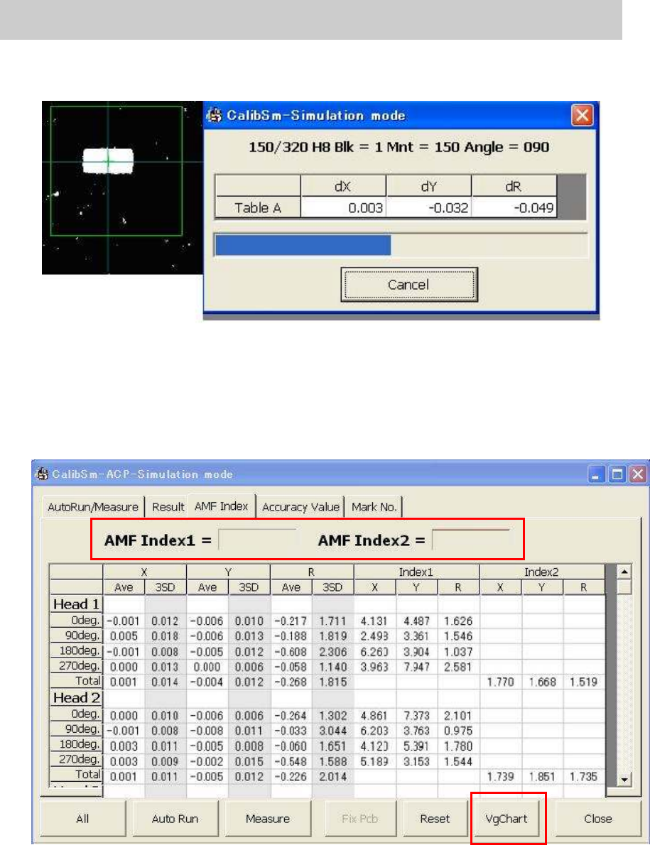
3. Start APC mounting measurement.
After changing the file name, click on the [Save (S)] button to perform mounting and
measurement in sequence.
Figure 50
4. Display the measured result. (“AMF Index” tab)
When the measurement is completed, the “AMF Index” screen is displayed.
If the measured result of “AMF index 1” is 1.0 or above, the adjustment does not need to be
performed.
If the result falls below “1.0”, the field turns red. Also the lowest Index value of each head is
indicated by boldface.
Figure 51
5. Check the values of the “AMF Index 1” and “AMF Index 2”.
Fill in the data as “The data before feedback” on the check sheet.
6. Click on the [VgChart] button.
Click on the [VgChart] button to check the adjustment state with the graphs.
Please refer to” 6.3 How to analyze the “VgChart” for how to interpret the graphs.
1.093 1.329